Measure the passage of time with MAX31334 and STM32F373VC
Add time management to your application

Published Feb 17, 2023
Click board™
RTC 19 Click
Dev. board
Fusion for STM32 v8
Compiler
NECTO Studio
MCU
STM32F373VC
Keep track of time in the right way and with the right tools
A
A
Hardware Overview
How does it work?
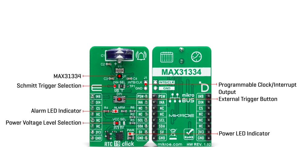
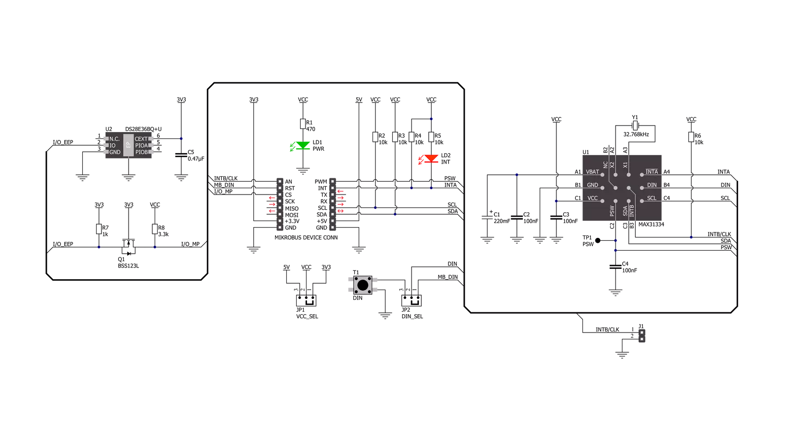
RTC 19 Click is based on the MAX31334, an ultra-low power, real-time clock (RTC) time-keeping device from Analog Devices. The MAX31334 is configured to transmit calendar and time data to the MCU (24-hour/12-hour format) based on a 32.768kHz quartz crystal and comes with an integrated interrupt generation function. It reads and writes clock/calendar data from and to the MCU in units ranging from seconds to the last two digits of the calendar year, providing seconds, minutes, hours, days, months, year, and date information. The end-of-the-month date is automatically adjusted for months with fewer than 31 days, including corrections for the leap year. The MAX31334 features an integrated high-side power pass switch (detectable through a PSW pin and drawn to the TP1 testpoint for external use), enabling idle, ultra-low power modes on duty-cycled applications by disconnecting power to other devices on the system. The power switch ON/OFF durations can be controlled by periodic
interrupt sources such as a countdown timer, alarms, or by an external interrupt from a DIN pushbutton. The DIN signal represents a digital Schmitt trigger that records timestamps or asserts an interrupt on its falling/rising edge. In addition to the DIN button, the state of this signal can also be changed digitally using the DIN pin, routed on the RST pin of the mikroBUS socket. The selection can be performed using an onboard SMD jumper labeled DIN SEL, placing it in an appropriate position marked as MB or T, where MB stands for mikroBUS and T for the button. This Click board communicates with MCU using the standard I2C 2-Wire interface to read data and configure settings, supporting a Fast Mode operation up to 400kHz. It also incorporates an alarm circuitry configured to generate a time-of-day/date interrupt signal. An alarm (interrupt) signal, marked as INA and routed to the INT pin of the mikroBUS socket, allows outputting warning every day or on a specific day visually
indicated by a red LED marked as ALARM. By utilizing an automatic backup switch, when the main supply drops below the programmed threshold voltage, this RTC can use an external power source (220mF supercapacitor), allowing uninterrupted operation. Besides an automatic backup switchover circuit, this board also carries a header for additional alarm/interrupt and a programmable clock output signal for frequencies from 1Hz to 32kHz available on an onboard J1 header. In addition, this signal also exists on the AN pin of the mikroBUS socket marked with INTB. This Click board™ can operate with either 3.3V or 5V logic voltage levels selected via the VCC SEL jumper. This way, both 3.3V and 5V capable MCUs can use the communication lines properly. However, the Click board™ comes equipped with a library containing easy-to-use functions and an example code that can be used, as a reference, for further development.
Features overview
Development board
Fusion for STM32 v8 is a development board specially designed for the needs of rapid development of embedded applications. It supports a wide range of microcontrollers, such as different 32-bit ARM® Cortex®-M based MCUs from STMicroelectronics, regardless of their number of pins, and a broad set of unique functions, such as the first-ever embedded debugger/programmer over WiFi. The development board is well organized and designed so that the end-user has all the necessary elements, such as switches, buttons, indicators, connectors, and others, in one place. Thanks to innovative manufacturing technology, Fusion for STM32 v8 provides a fluid and immersive working experience, allowing
access anywhere and under any circumstances at any time. Each part of the Fusion for STM32 v8 development board contains the components necessary for the most efficient operation of the same board. An advanced integrated CODEGRIP programmer/debugger module offers many valuable programming/debugging options, including support for JTAG, SWD, and SWO Trace (Single Wire Output)), and seamless integration with the Mikroe software environment. Besides, it also includes a clean and regulated power supply module for the development board. It can use a wide range of external power sources, including a battery, an external 12V power supply, and a power source via the USB Type-C (USB-C) connector.
Communication options such as USB-UART, USB HOST/DEVICE, CAN (on the MCU card, if supported), and Ethernet is also included. In addition, it also has the well-established mikroBUS™ standard, a standardized socket for the MCU card (SiBRAIN standard), and two display options for the TFT board line of products and character-based LCD. Fusion for STM32 v8 is an integral part of the Mikroe ecosystem for rapid development. Natively supported by Mikroe software tools, it covers many aspects of prototyping and development thanks to a considerable number of different Click boards™ (over a thousand boards), the number of which is growing every day.

Microcontroller Overview
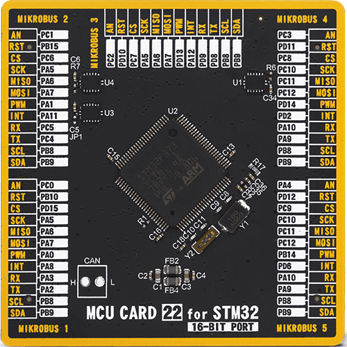
MCU Card / MCU
Type
8th Generation
Architecture
ARM Cortex-M4
MCU Memory (KB)
256
Silicon Vendor
STMicroelectronics
Pin count
100
RAM (Bytes)
49152
Used MCU Pins
mikroBUS™ mapper
Take a closer look
Click board™ Schematic
Step by step
Project assembly

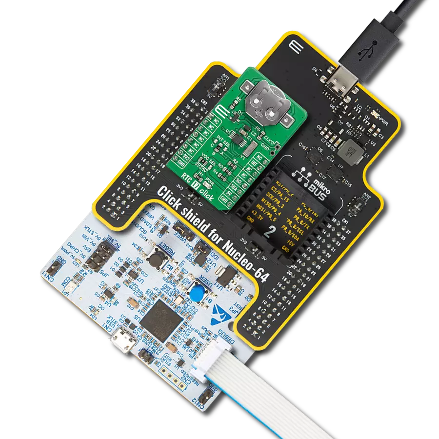
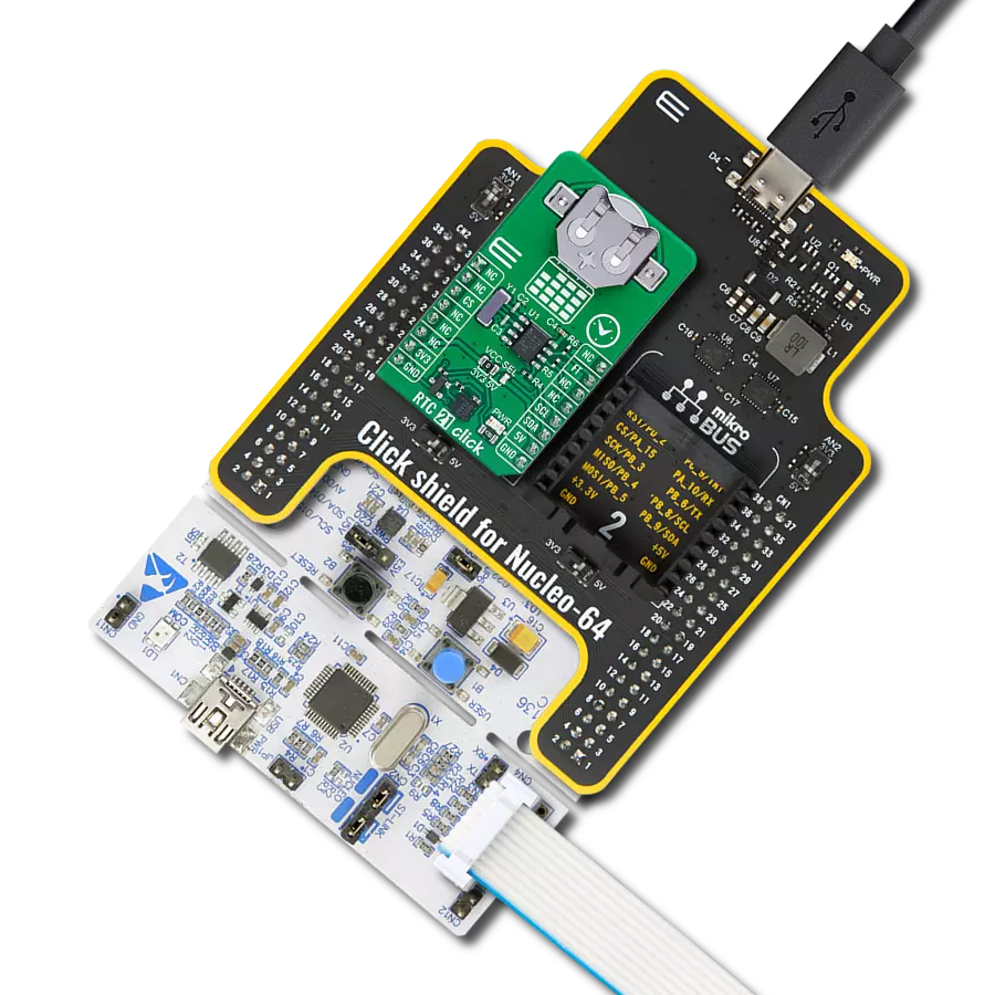
Start by selecting your development board and Click board™. Begin with the Fusion for STM32 v8 as your development board.


Track your results in real time
Application Output
1. Application Output - In Debug mode, the 'Application Output' window enables real-time data monitoring, offering direct insight into execution results. Ensure proper data display by configuring the environment correctly using the provided tutorial.

2. UART Terminal - Use the UART Terminal to monitor data transmission via a USB to UART converter, allowing direct communication between the Click board™ and your development system. Configure the baud rate and other serial settings according to your project's requirements to ensure proper functionality. For step-by-step setup instructions, refer to the provided tutorial.

3. Plot Output - The Plot feature offers a powerful way to visualize real-time sensor data, enabling trend analysis, debugging, and comparison of multiple data points. To set it up correctly, follow the provided tutorial, which includes a step-by-step example of using the Plot feature to display Click board™ readings. To use the Plot feature in your code, use the function: plot(*insert_graph_name*, variable_name);. This is a general format, and it is up to the user to replace 'insert_graph_name' with the actual graph name and 'variable_name' with the parameter to be displayed.

Software Support
Library Description
This library contains API for RTC 19 Click driver.
Key functions:
rtc19_set_timeThis function sets the starting time values - second, minute and hour.rtc19_read_timeThis function reads the current time values - second, minute and hour.rtc19_read_dateThis function reads the current date values - day of week, day, month and year.
Open Source
Code example
The complete application code and a ready-to-use project are available through the NECTO Studio Package Manager for direct installation in the NECTO Studio. The application code can also be found on the MIKROE GitHub account.
/*!
 * @file main.c
 * @brief RTC 19 Click example
 *
 * # Description
 * This example demonstrates the use of RTC 19 Click board by reading and displaying
 * the time and date values.
 *
 * The demo application is composed of two sections :
 *
 * ## Application Init
 * Initializes the driver and logger and performs the Click default configuration
 * which resets the device and sets the timer interrupt to 1 Hz.
 * After that, it sets the starting time and date.
 *
 * ## Application Task
 * Waits for a timer countdown interrupt (1 Hz) and then reads and displays on the USB UART
 * the current time and date values.
 *
 * @author Stefan Filipovic
 *
 */

#include "board.h"
#include "log.h"
#include "rtc19.h"

static rtc19_t rtc19;
static log_t logger;
static rtc19_time_t time;
static rtc19_date_t date;

/**
 * @brief RTC 19 get day of week name function.
 * @details This function returns the name of day of the week as a string.
 * @param[in] ctx : Click context object.
 * See #rtc19_t object definition for detailed explanation.
 * @param[in] day_of_week : Day of week decimal value.
 * @return Name of day as a string.
 * @note None.
 */
static char *rtc19_get_day_of_week_name ( uint8_t day_of_week );

void application_init ( void )
{
    log_cfg_t log_cfg;  /**< Logger config object. */
    rtc19_cfg_t rtc19_cfg;  /**< Click config object. */

    /**
     * Logger initialization.
     * Default baud rate: 115200
     * Default log level: LOG_LEVEL_DEBUG
     * @note If USB_UART_RX and USB_UART_TX
     * are defined as HAL_PIN_NC, you will
     * need to define them manually for log to work.
     * See @b LOG_MAP_USB_UART macro definition for detailed explanation.
     */
    LOG_MAP_USB_UART( log_cfg );
    log_init( &logger, &log_cfg );
    log_info( &logger, " Application Init " );

    // Click initialization.
    rtc19_cfg_setup( &rtc19_cfg );
    RTC19_MAP_MIKROBUS( rtc19_cfg, MIKROBUS_1 );
    if ( I2C_MASTER_ERROR == rtc19_init( &rtc19, &rtc19_cfg ) )
    {
        log_error( &logger, " Communication init." );
        for ( ; ; );
    }

    if ( RTC19_ERROR == rtc19_default_cfg ( &rtc19 ) )
    {
        log_error( &logger, " Default configuration." );
        for ( ; ; );
    }

    time.hour = 23;
    time.minute = 59;
    time.second = 50;
    if ( RTC19_OK == rtc19_set_time ( &rtc19, &time ) )
    {
        log_printf( &logger, " Set time: %.2u:%.2u:%.2u\r\n",
                    ( uint16_t ) time.hour, ( uint16_t ) time.minute, ( uint16_t ) time.second );
    }
    date.day_of_week = RTC19_SATURDAY;
    date.day = 31;
    date.month = 12;
    date.year = 22;
    if ( RTC19_OK == rtc19_set_date ( &rtc19, &date ) )
    {
        log_printf( &logger, " Set date: %s, %.2u.%.2u.20%.2u.\r\n",
                    rtc19_get_day_of_week_name ( date.day_of_week ),
                    ( uint16_t ) date.day, ( uint16_t ) date.month, ( uint16_t ) date.year );
    }

    log_info( &logger, " Application Task " );
}

void application_task ( void )
{
    // Wait for a timer countdown flag configured at 1 Hz
    while ( rtc19_get_inta_pin ( &rtc19 ) );

    Delay_ms ( 100 );
    rtc19_clear_interrupts ( &rtc19 );
    if ( RTC19_OK == rtc19_read_time ( &rtc19, &time ) )
    {
        log_printf( &logger, " Time: %.2u:%.2u:%.2u\r\n",
                    ( uint16_t ) time.hour, ( uint16_t ) time.minute, ( uint16_t ) time.second );
    }
    if ( RTC19_OK == rtc19_read_date ( &rtc19, &date ) )
    {
        log_printf( &logger, " Date: %s, %.2u.%.2u.20%.2u.\r\n",
                    rtc19_get_day_of_week_name ( date.day_of_week ),
                    ( uint16_t ) date.day, ( uint16_t ) date.month, ( uint16_t ) date.year );
    }
}

int main ( void )
{
    /* Do not remove this line or clock might not be set correctly. */
    #ifdef PREINIT_SUPPORTED
    preinit();
    #endif

    application_init( );

    for ( ; ; )
    {
        application_task( );
    }

    return 0;
}

static char *rtc19_get_day_of_week_name ( uint8_t day_of_week )
{
    switch ( day_of_week )
    {
        case RTC19_MONDAY:
        {
            return "Monday";
        }
        case RTC19_TUESDAY:
        {
            return "Tuesday";
        }
        case RTC19_WEDNESDAY:
        {
            return "Wednesday";
        }
        case RTC19_THURSDAY:
        {
            return "Thursday";
        }
        case RTC19_FRIDAY:
        {
            return "Friday";
        }
        case RTC19_SATURDAY:
        {
            return "Saturday";
        }
        case RTC19_SUNDAY:
        {
            return "Sunday";
        }
        default:
        {
            return "Unknown";
        }
    }
}

// ------------------------------------------------------------------------ END