Accurately detect speed and direction of rotation or linear movement with AH3965 and STM32G474RE
Precise speed and direction detection solution based on Hall effect for industrial applications

Published May 22, 2025
Click board™
Hall Switch 5 Click
Dev. board
Nucleo 64 with STM32G474RE MCU
Compiler
NECTO Studio
MCU
STM32G474RE
Detect speed and direction of rotation or linear movement with dual Hall effect sensing
A
A
Hardware Overview
How does it work?
Hall Switch 5 Click is based on the AH3965, a high-voltage dual Hall effect sensor from Diodes Incorporated designed for precise speed and direction sensing. This sensor uses a chopper-stabilized architecture paired with an internal bandgap regulator to ensure consistent performance across a wide temperature range, enabling reliable operation in demanding industrial environments. The AH3965 generates two key outputs - speed and direction - accessible through the SP and DIR pins, providing a dependable solution for motion detection systems. To protect internal circuitry and ensure robustness, the sensor incorporates a reverse blocking diode and a Zener clamp on the supply line. In scenarios where the supply voltage drops below the minimum operational threshold, the sensor’s undervoltage lockout mechanism activates, freezing operation to prevent measurement errors and ensure that the output is only updated with accurate, validated magnetic data. The AH3965 is finely tuned to respond to specific magnetic thresholds, with an operating point ranging from -10 to 30 Gauss
(typically 10 Gauss), a release point from -30 to 10 Gauss (typically -10 Gauss), and a magnetic offset tolerance of ±15 Gauss. It maintains magnetic matching within ±25 Gauss, ensuring consistent detection performance across applications. This makes Hall Switch 5 Click an excellent choice for a range of motion-related applications, including industrial motors, pump systems, white goods, and systems that require detection of rotational or linear speed and direction, as well as angular position tracking. This Click board™ is designed in a unique format supporting the newly introduced MIKROE feature called "Click Snap." Unlike the standardized version of Click boards, this feature allows the main sensor area to become movable by breaking the PCB, opening up many new possibilities for implementation. Thanks to the Snap feature, the AH3965 can operate autonomously by accessing its signals directly on the pins marked 1-8. Additionally, the Snap part includes a specified and fixed screw hole position, enabling users to secure the Snap board in their desired location. To support development and testing, Hall Switch 5 Click can
be used with an optional rotary magnetic holder, sold separately, which achieves efficient prototyping. This tool features an adjustable shaft fitted with a 6mm diameter magnet that can be aligned directly above the Hall effect sensor. When the magnet moves in the positive x-axis direction - indicating a south pole approaching the sensor’s surface - the south magnetic field strength increases. Movement toward zero indicates a reduction in this field, while movement in the negative x-axis direction corresponds to the north pole approaching the sensor’s marking surface. This precise control and feedback setup enables engineers to quickly evaluate the sensor’s behavior in real-time and streamline their design process. This Click board™ can operate with either 3.3V or 5V logic voltage levels selected via the VCC SEL jumper. This way, both 3.3V and 5V capable MCUs can use the communication lines properly. Also, this Click board™ comes equipped with a library containing easy-to-use functions and an example code that can be used as a reference for further development.

Features overview
Development board
Nucleo-64 with STM32G474R MCU offers a cost-effective and adaptable platform for developers to explore new ideas and prototype their designs. This board harnesses the versatility of the STM32 microcontroller, enabling users to select the optimal balance of performance and power consumption for their projects. It accommodates the STM32 microcontroller in the LQFP64 package and includes essential components such as a user LED, which doubles as an ARDUINO® signal, alongside user and reset push-buttons, and a 32.768kHz crystal oscillator for precise timing operations. Designed with expansion and flexibility in mind, the Nucleo-64 board features an ARDUINO® Uno V3 expansion connector and ST morpho extension pin
headers, granting complete access to the STM32's I/Os for comprehensive project integration. Power supply options are adaptable, supporting ST-LINK USB VBUS or external power sources, ensuring adaptability in various development environments. The board also has an on-board ST-LINK debugger/programmer with USB re-enumeration capability, simplifying the programming and debugging process. Moreover, the board is designed to simplify advanced development with its external SMPS for efficient Vcore logic supply, support for USB Device full speed or USB SNK/UFP full speed, and built-in cryptographic features, enhancing both the power efficiency and security of projects. Additional connectivity is
provided through dedicated connectors for external SMPS experimentation, a USB connector for the ST-LINK, and a MIPI® debug connector, expanding the possibilities for hardware interfacing and experimentation. Developers will find extensive support through comprehensive free software libraries and examples, courtesy of the STM32Cube MCU Package. This, combined with compatibility with a wide array of Integrated Development Environments (IDEs), including IAR Embedded Workbench®, MDK-ARM, and STM32CubeIDE, ensures a smooth and efficient development experience, allowing users to fully leverage the capabilities of the Nucleo-64 board in their projects.

Microcontroller Overview
MCU Card / MCU

Architecture
ARM Cortex-M4
MCU Memory (KB)
512
Silicon Vendor
STMicroelectronics
Pin count
64
RAM (Bytes)
128k
You complete me!
Accessories
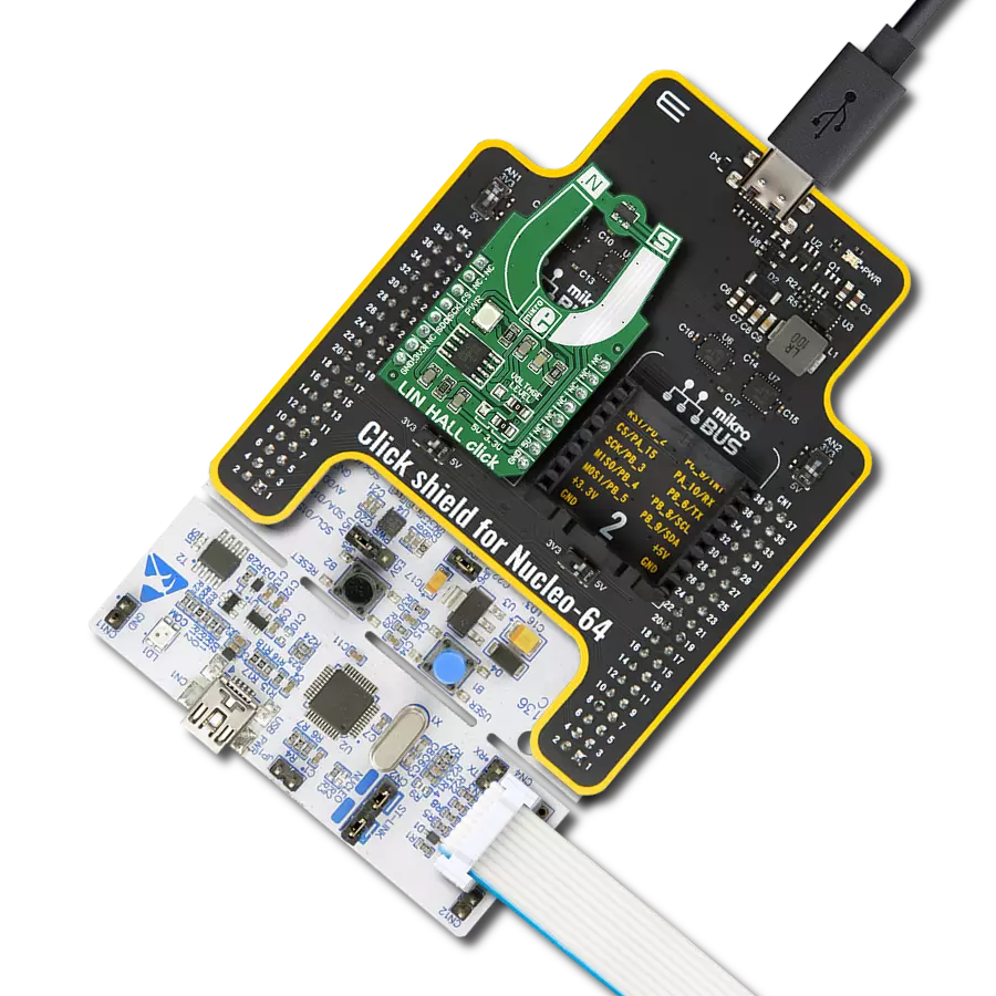
Click Shield for Nucleo-64 comes equipped with two proprietary mikroBUS™ sockets, allowing all the Click board™ devices to be interfaced with the STM32 Nucleo-64 board with no effort. This way, Mikroe allows its users to add any functionality from our ever-growing range of Click boards™, such as WiFi, GSM, GPS, Bluetooth, ZigBee, environmental sensors, LEDs, speech recognition, motor control, movement sensors, and many more. More than 1537 Click boards™, which can be stacked and integrated, are at your disposal. The STM32 Nucleo-64 boards are based on the microcontrollers in 64-pin packages, a 32-bit MCU with an ARM Cortex M4 processor operating at 84MHz, 512Kb Flash, and 96KB SRAM, divided into two regions where the top section represents the ST-Link/V2 debugger and programmer while the bottom section of the board is an actual development board. These boards are controlled and powered conveniently through a USB connection to program and efficiently debug the Nucleo-64 board out of the box, with an additional USB cable connected to the USB mini port on the board. Most of the STM32 microcontroller pins are brought to the IO pins on the left and right edge of the board, which are then connected to two existing mikroBUS™ sockets. This Click Shield also has several switches that perform functions such as selecting the logic levels of analog signals on mikroBUS™ sockets and selecting logic voltage levels of the mikroBUS™ sockets themselves. Besides, the user is offered the possibility of using any Click board™ with the help of existing bidirectional level-shifting voltage translators, regardless of whether the Click board™ operates at a 3.3V or 5V logic voltage level. Once you connect the STM32 Nucleo-64 board with our Click Shield for Nucleo-64, you can access hundreds of Click boards™, working with 3.3V or 5V logic voltage levels.

Rotary Magnetic Holder is an addition designed for use alongside a magnetic rotary position sensor. It comes with a plastic stand measuring 22x16x10 millimeters (L x W x H), as well as an adjustable shaft with a 6mm diameter magnet. The plastic frame has four round feet that fit into holes in the board near the magnetic rotary position sensor, with a 6mm diameter hole on top to match the adjustable shaft that carries the magnet. This shaft has a height adjustment screw on it, allowing the user to adjust it between 18 and 22 millimeters. This way, fast prototyping and quick measurements of the magnet characteristics are allowed during development.

Used MCU Pins
mikroBUS™ mapper
Take a closer look
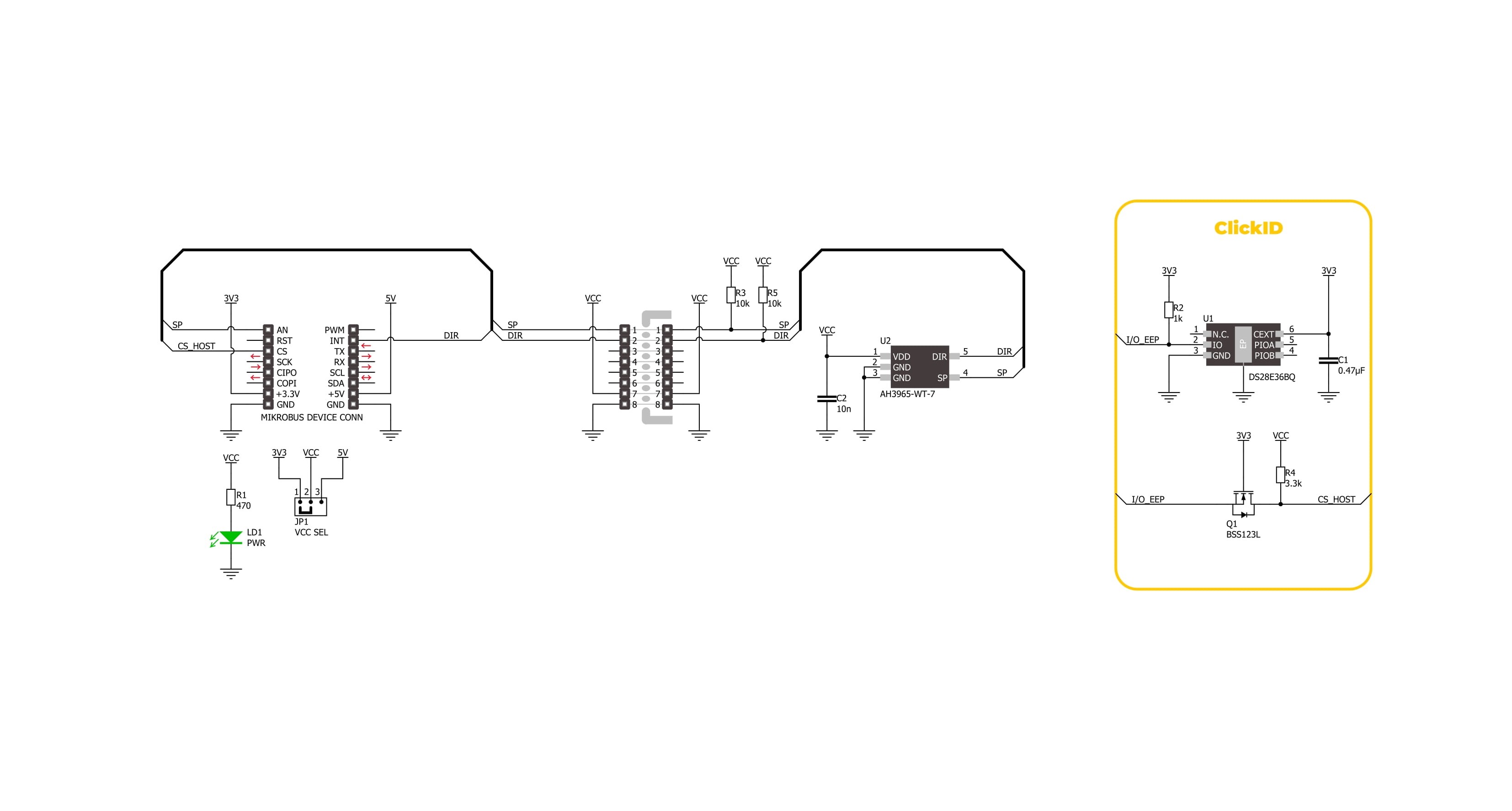
Click board™ Schematic
Step by step
Project assembly
Start by selecting your development board and Click board™. Begin with the Nucleo 64 with STM32G474RE MCU as your development board.


Track your results in real time
Application Output
1. Application Output - In Debug mode, the 'Application Output' window enables real-time data monitoring, offering direct insight into execution results. Ensure proper data display by configuring the environment correctly using the provided tutorial.

2. UART Terminal - Use the UART Terminal to monitor data transmission via a USB to UART converter, allowing direct communication between the Click board™ and your development system. Configure the baud rate and other serial settings according to your project's requirements to ensure proper functionality. For step-by-step setup instructions, refer to the provided tutorial.

3. Plot Output - The Plot feature offers a powerful way to visualize real-time sensor data, enabling trend analysis, debugging, and comparison of multiple data points. To set it up correctly, follow the provided tutorial, which includes a step-by-step example of using the Plot feature to display Click board™ readings. To use the Plot feature in your code, use the function: plot(*insert_graph_name*, variable_name);. This is a general format, and it is up to the user to replace 'insert_graph_name' with the actual graph name and 'variable_name' with the parameter to be displayed.

Software Support
Library Description
Hall Switch 5 Click demo application is developed using the NECTO Studio, ensuring compatibility with mikroSDK's open-source libraries and tools. Designed for plug-and-play implementation and testing, the demo is fully compatible with all development, starter, and mikromedia boards featuring a mikroBUS™ socket.
Example Description
This example demonstrates the use of the Hall Switch 5 Click board by initializing the device and detecting changes in rotational direction and speed. It logs the direction (Clockwise or Counter-Clockwise) and speed in Hertz every second.
Key functions:
hallswitch5_cfg_setup- This function initializes Click configuration structure to initial values.hallswitch5_init- This function initializes all necessary pins and peripherals used for this Click board.hallswitch5_get_speed_pin- This function reads the state of the SPEED pin of Hall Switch 5 Click board.hallswitch5_get_dir_pin- This function reads the state of the DIR pin of Hall Switch 5 Click board.
Application Init
Initializes the logger and the Hall Switch 5 Click driver.
Application Task
Reads the direction and speed pins periodically, logs the rotational direction and calculates the speed in Hz, which is displayed every second.
Open Source
Code example
The complete application code and a ready-to-use project are available through the NECTO Studio Package Manager for direct installation in the NECTO Studio. The application code can also be found on the MIKROE GitHub account.
/*!
 * @file main.c
 * @brief Hall Switch 5 Click Example.
 *
 * # Description
 * This example demonstrates the use of the Hall Switch 5 Click board by initializing
 * the device and detecting changes in rotational direction and speed. It logs the
 * direction (Clockwise or Counter-Clockwise) and speed in Hertz every second.
 *
 * The demo application is composed of two sections:
 *
 * ## Application Init
 * Initializes the logger and the Hall Switch 5 Click driver.
 *
 * ## Application Task
 * Reads the direction and speed pins periodically, logs the rotational direction
 * and calculates the speed in Hz, which is displayed every second.
 *
 * @author Stefan Filipovic
 *
 */

#include "board.h"
#include "log.h"
#include "hallswitch5.h"

static hallswitch5_t hallswitch5;   /**< Hall Switch 5 Click driver object. */
static log_t logger;                /**< Logger object. */

void application_init ( void )
{
    log_cfg_t log_cfg;  /**< Logger config object. */
    hallswitch5_cfg_t hallswitch5_cfg;  /**< Click config object. */

    /**
     * Logger initialization.
     * Default baud rate: 115200
     * Default log level: LOG_LEVEL_DEBUG
     * @note If USB_UART_RX and USB_UART_TX
     * are defined as HAL_PIN_NC, you will
     * need to define them manually for log to work.
     * See @b LOG_MAP_USB_UART macro definition for detailed explanation.
     */
    LOG_MAP_USB_UART( log_cfg );
    log_init( &logger, &log_cfg );
    log_info( &logger, " Application Init " );

    // Click initialization.
    hallswitch5_cfg_setup( &hallswitch5_cfg );
    HALLSWITCH5_MAP_MIKROBUS( hallswitch5_cfg, MIKROBUS_1 );
    if ( DIGITAL_OUT_UNSUPPORTED_PIN == hallswitch5_init( &hallswitch5, &hallswitch5_cfg ) )
    {
        log_error( &logger, " Communication init." );
        for ( ; ; );
    }

    log_info( &logger, " Application Task " );
}

void application_task ( void )
{
    static uint8_t direction_old = 0xFF;
    static uint8_t speed_old = HALLSWITCH5_PIN_LOW;
    static uint8_t num_toggles = 0;
    static uint32_t period_ms = 0;
    uint8_t direction = hallswitch5_get_dir_pin ( &hallswitch5 );
    uint8_t speed = hallswitch5_get_speed_pin ( &hallswitch5 );
    if ( direction != direction_old )
    {
        direction_old = direction;
        log_printf ( &logger, " Direction: %s\r\n",
                    ( char * ) ( ( direction == HALLSWITCH5_DIR_CW ) ? "CW" : "CCW" ) );
    }
    if ( speed_old != speed )
    {
        speed_old = speed;
        num_toggles++;
    }
    if ( ++period_ms > 1000 )
    {
        log_printf ( &logger, " Speed: %.1f Hz\r\n", ( float ) num_toggles / 2 );
        num_toggles = 0;
        period_ms = 0;
    }
    Delay_1ms ( );
}

int main ( void )
{
    /* Do not remove this line or clock might not be set correctly. */
    #ifdef PREINIT_SUPPORTED
    preinit();
    #endif

    application_init( );

    for ( ; ; )
    {
        application_task( );
    }

    return 0;
}

// ------------------------------------------------------------------------ END
Additional Support
Resources
Category:Magnetic