Implement capacitive sliding interface with IQS323 and STM32G474RE
Capacitive slider solution for intuitive, low-power gesture control in embedded systems

Published Aug 13, 2025
Click board™
Cap Slider 3 Click
Dev. board
Nucleo 64 with STM32G474RE MCU
Compiler
NECTO Studio
MCU
STM32G474RE
Capacitive slide gesture detection with ultra-low power operation and noise immunity for intuitive touch-based control
A
A
Hardware Overview
How does it work?
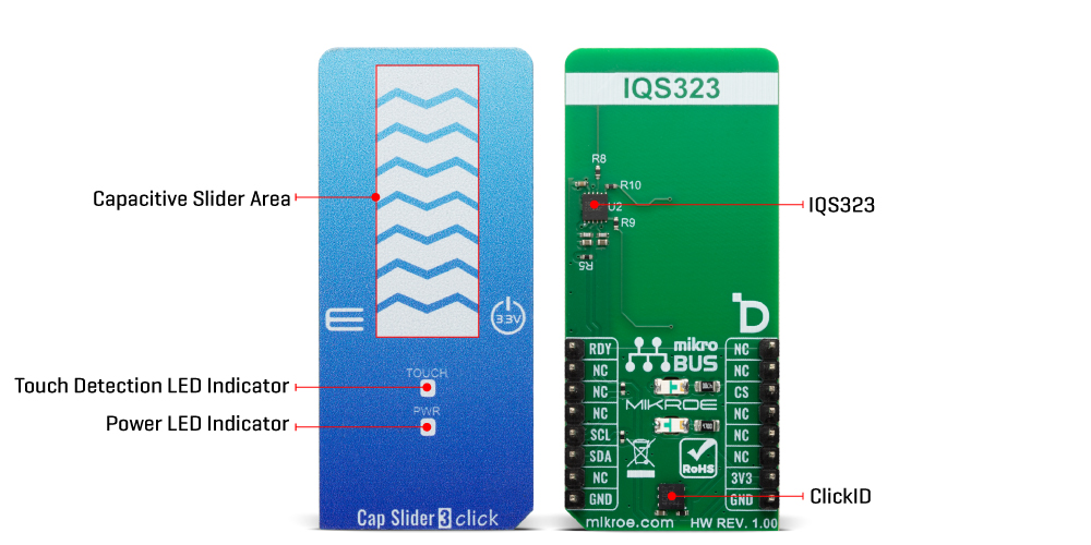
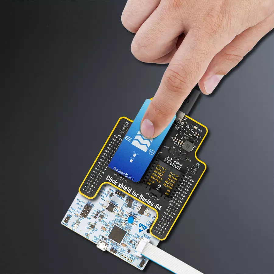
Cap Slider 3 Click is based on the IQS323, a highly flexible ProxFusion® sensor fusion IC from Azoteq, designed to provide a reliable capacitive sliding interface for various touch-based control applications. The front side of the board incorporates a single large sensor pad that allows for intuitive sliding gestures, providing a smooth user experience. The IQS323 communicates over the standard I2C interface and performs all processing on-chip, allowing it to function effectively even in ultra-low-power modes. The built-in feature set includes automatic tuning for optimal sensitivity under varying environmental conditions, advanced noise filtering for stable readings, and differential measurement support via reference channels to improve accuracy. The IQS323 also integrates debounce and hysteresis mechanisms to prevent false triggers, as well as dual-direction trigger indication for clear response
to sliding gestures in both directions. Additionally, the IQS323 supports a Halt Mode that significantly reduces power consumption, along with a distributed ultra-low-power (ULP) mode that intelligently balances response time and energy efficiency. These features make Cap Slider 3 Click an ideal solution for applications that require robust, low-power touch or proximity interfaces such as wearable electronics like fitness bands and smartwatches, presence or wear detection mechanisms, SAR (Specific Absorption Rate) safety sensors, and wake-up buttons in battery-powered systems. As mentioned earlier, this Click contains a 3-segment capacitive sensing slider that can detect a slide in either the UP or DOWN direction, as well as two LED indicators (TOUCH and PWR). These are the only elements on the top side of the board, allowing the protective acrylic plexiglass layer placement. If a touch event is
detected on slider area, the state of the TOUCH LED will be changed, indicating an activated channel; more precisely, touch has been detected on that specific field. Cap Slider 3 Click communicates with MCU using the standard I2C 2-Wire interface with a maximum clock frequency of 1MHz, fully adjustable through software registers. An additional ready signal, routed on the RDY pin of the mikroBUS™ socket, is added, which indicates when the communication window is available with new data for optimal response. Thus, it is optimal for the response rate to use the INT pin as a communication trigger. This Click board™ can be operated only with a 3.3V logic voltage level. The board must perform appropriate logic voltage level conversion before using MCUs with different logic levels. It also comes equipped with a library containing functions and example code that can be used as a reference for further development.
Features overview
Development board
Nucleo-64 with STM32G474R MCU offers a cost-effective and adaptable platform for developers to explore new ideas and prototype their designs. This board harnesses the versatility of the STM32 microcontroller, enabling users to select the optimal balance of performance and power consumption for their projects. It accommodates the STM32 microcontroller in the LQFP64 package and includes essential components such as a user LED, which doubles as an ARDUINO® signal, alongside user and reset push-buttons, and a 32.768kHz crystal oscillator for precise timing operations. Designed with expansion and flexibility in mind, the Nucleo-64 board features an ARDUINO® Uno V3 expansion connector and ST morpho extension pin
headers, granting complete access to the STM32's I/Os for comprehensive project integration. Power supply options are adaptable, supporting ST-LINK USB VBUS or external power sources, ensuring adaptability in various development environments. The board also has an on-board ST-LINK debugger/programmer with USB re-enumeration capability, simplifying the programming and debugging process. Moreover, the board is designed to simplify advanced development with its external SMPS for efficient Vcore logic supply, support for USB Device full speed or USB SNK/UFP full speed, and built-in cryptographic features, enhancing both the power efficiency and security of projects. Additional connectivity is
provided through dedicated connectors for external SMPS experimentation, a USB connector for the ST-LINK, and a MIPI® debug connector, expanding the possibilities for hardware interfacing and experimentation. Developers will find extensive support through comprehensive free software libraries and examples, courtesy of the STM32Cube MCU Package. This, combined with compatibility with a wide array of Integrated Development Environments (IDEs), including IAR Embedded Workbench®, MDK-ARM, and STM32CubeIDE, ensures a smooth and efficient development experience, allowing users to fully leverage the capabilities of the Nucleo-64 board in their projects.

Microcontroller Overview
MCU Card / MCU

Architecture
ARM Cortex-M4
MCU Memory (KB)
512
Silicon Vendor
STMicroelectronics
Pin count
64
RAM (Bytes)
128k
You complete me!
Accessories
Click Shield for Nucleo-64 comes equipped with two proprietary mikroBUS™ sockets, allowing all the Click board™ devices to be interfaced with the STM32 Nucleo-64 board with no effort. This way, Mikroe allows its users to add any functionality from our ever-growing range of Click boards™, such as WiFi, GSM, GPS, Bluetooth, ZigBee, environmental sensors, LEDs, speech recognition, motor control, movement sensors, and many more. More than 1537 Click boards™, which can be stacked and integrated, are at your disposal. The STM32 Nucleo-64 boards are based on the microcontrollers in 64-pin packages, a 32-bit MCU with an ARM Cortex M4 processor operating at 84MHz, 512Kb Flash, and 96KB SRAM, divided into two regions where the top section represents the ST-Link/V2 debugger and programmer while the bottom section of the board is an actual development board. These boards are controlled and powered conveniently through a USB connection to program and efficiently debug the Nucleo-64 board out of the box, with an additional USB cable connected to the USB mini port on the board. Most of the STM32 microcontroller pins are brought to the IO pins on the left and right edge of the board, which are then connected to two existing mikroBUS™ sockets. This Click Shield also has several switches that perform functions such as selecting the logic levels of analog signals on mikroBUS™ sockets and selecting logic voltage levels of the mikroBUS™ sockets themselves. Besides, the user is offered the possibility of using any Click board™ with the help of existing bidirectional level-shifting voltage translators, regardless of whether the Click board™ operates at a 3.3V or 5V logic voltage level. Once you connect the STM32 Nucleo-64 board with our Click Shield for Nucleo-64, you can access hundreds of Click boards™, working with 3.3V or 5V logic voltage levels.

Used MCU Pins
mikroBUS™ mapper
Take a closer look
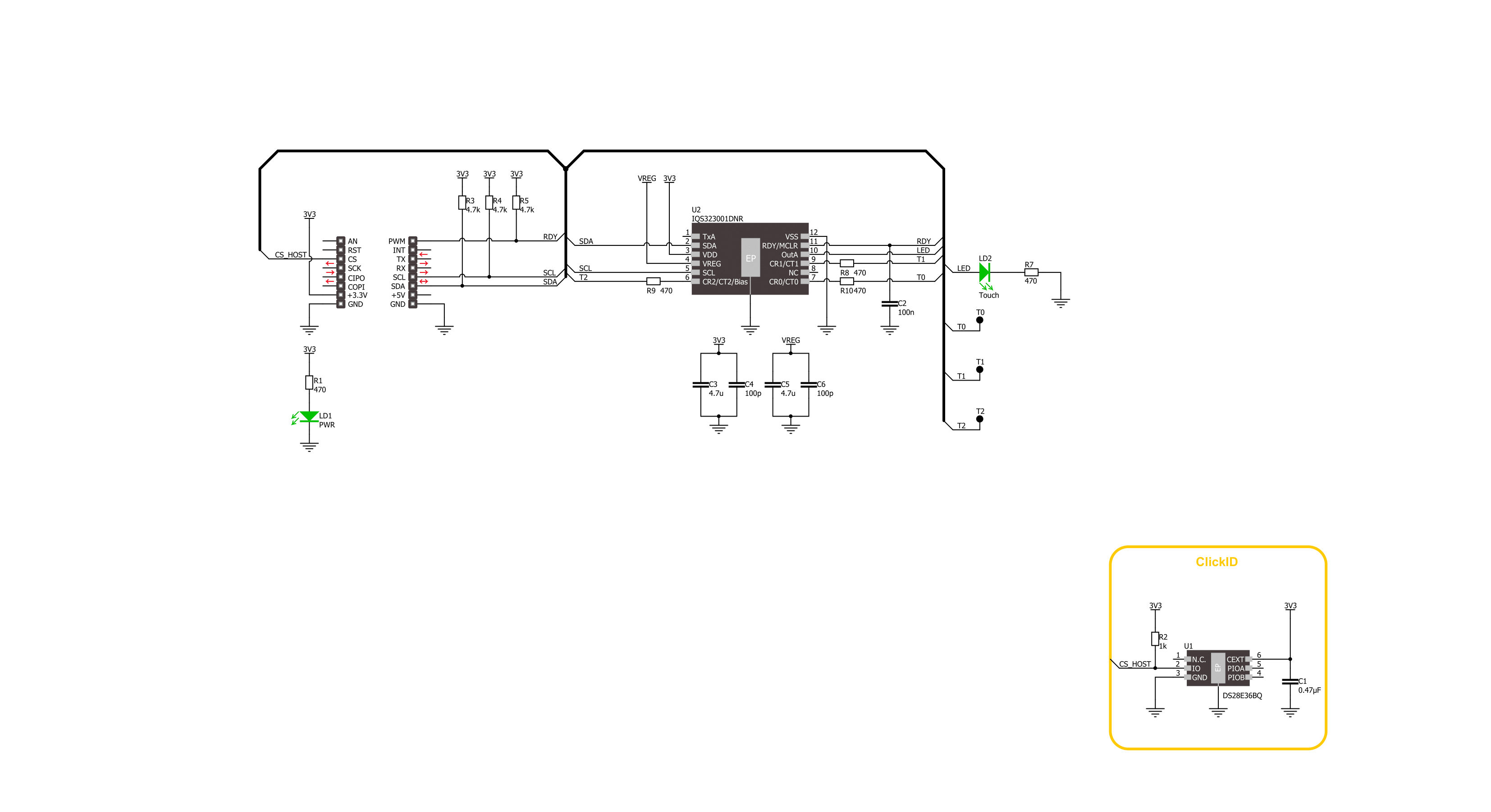
Click board™ Schematic
Step by step
Project assembly
Start by selecting your development board and Click board™. Begin with the Nucleo 64 with STM32G474RE MCU as your development board.


Software Support
Library Description
Cap Slider 3 Click demo application is developed using the NECTO Studio, ensuring compatibility with mikroSDK's open-source libraries and tools. Designed for plug-and-play implementation and testing, the demo is fully compatible with all development, starter, and mikromedia boards featuring a mikroBUS™ socket.
Example Description
This example demonstrates the use of the Cap Slider 3 Click board by initializing the device and reading the current slider position. The application logs the detected slider position in real-time.
Key functions:
capslider3_cfg_setup- This function initializes Click configuration structure to initial values.capslider3_init- This function initializes all necessary pins and peripherals used for this Click board.capslider3_default_cfg- This function executes a default configuration of Cap Slider 3 Click board.capslider3_read_data- This function reads various system information and sensor data from the Click board.
Application Init
Initializes the logger and the Cap Slider 3 Click driver.
Application Task
Continuously reads and logs the slider position detected by the Cap Slider 3 Click board.
Open Source
Code example
The complete application code and a ready-to-use project are available through the NECTO Studio Package Manager for direct installation in the NECTO Studio. The application code can also be found on the MIKROE GitHub account.
/*!
 * @file main.c
 * @brief Cap Slider 3 Click example
 *
 * # Description
 * This example demonstrates the use of the Cap Slider 3 Click board by initializing
 * the device and reading the current slider position. The application logs the detected
 * slider position in real-time.
 *
 * The demo application is composed of two sections:
 *
 * ## Application Init
 * Initializes the logger and the Cap Slider 3 Click driver.
 *
 * ## Application Task
 * Continuously reads and logs the slider position detected by the Cap Slider 3 Click board.
 *
 * @note
 * Functions for logging gestures and statuses are available but not used in this example.
 *
 * @author Stefan Filipovic
 *
 */


#include "board.h"
#include "log.h"
#include "capslider3.h"

static capslider3_t capslider3;
static log_t logger;

/**
 * @brief Cap Slider 3 log status function.
 * @details This function logs the power mode, touch, and proximity status of the Cap Slider 3 Click board.
 * @param[in] status : Status data to be logged (sys_info.sys_status).
 * @note None.
 */
static void capslider3_log_status ( uint16_t status );

/**
 * @brief Cap Slider 3 log gesture function.
 * @details This function logs the detected gestures of the Cap Slider 3 Click board.
 * @param[in] gesture : Gesture data to be logged (sys_info.gestures).
 * @note None.
 */
static void capslider3_log_gesture ( uint16_t gesture );

void application_init ( void )
{
    log_cfg_t log_cfg;  /**< Logger config object. */
    capslider3_cfg_t capslider3_cfg;  /**< Click config object. */

    /**
     * Logger initialization.
     * Default baud rate: 115200
     * Default log level: LOG_LEVEL_DEBUG
     * @note If USB_UART_RX and USB_UART_TX
     * are defined as HAL_PIN_NC, you will
     * need to define them manually for log to work.
     * See @b LOG_MAP_USB_UART macro definition for detailed explanation.
     */
    LOG_MAP_USB_UART( log_cfg );
    log_init( &logger, &log_cfg );
    log_info( &logger, " Application Init " );

    // Click initialization.
    capslider3_cfg_setup( &capslider3_cfg );
    CAPSLIDER3_MAP_MIKROBUS( capslider3_cfg, MIKROBUS_1 );
    if ( I2C_MASTER_ERROR == capslider3_init( &capslider3, &capslider3_cfg ) )
    {
        log_error( &logger, " Communication init." );
        for ( ; ; );
    }

    if ( CAPSLIDER3_ERROR == capslider3_default_cfg ( &capslider3 ) )
    {
        log_error( &logger, " Default configuration." );
        for ( ; ; );
    }

    log_info( &logger, " Application Task " );
}

void application_task ( void )
{
    capslider3_data_t sys_info;
    if ( CAPSLIDER3_OK == capslider3_read_data ( &capslider3, &sys_info ) )
    {
        if ( CAPSLIDER3_SLIDER_IDLE != sys_info.slider )
        {
            log_printf ( &logger, " Slider: - %u -\r\n\n", sys_info.slider );
        }
    }
}

int main ( void )
{
    /* Do not remove this line or clock might not be set correctly. */
    #ifdef PREINIT_SUPPORTED
    preinit();
    #endif

    application_init( );

    for ( ; ; )
    {
        application_task( );
    }

    return 0;
}

static void capslider3_log_status ( uint16_t status )
{
    log_printf ( &logger, "--- STATUS ---\r\n" );
    log_printf ( &logger, " Power mode: " );
    switch ( status & CAPSLIDER3_SYSTEM_STATUS_POWER_MODE_MASK )
    {
        case CAPSLIDER3_SYSTEM_STATUS_POWER_MODE_NORMAL:
        {
            log_printf ( &logger, "NORMAL" );
            break;
        }
        case CAPSLIDER3_SYSTEM_STATUS_POWER_MODE_LP:
        {
            log_printf ( &logger, "LOW POWER" );
            break;
        }
        case CAPSLIDER3_SYSTEM_STATUS_POWER_MODE_ULP:
        {
            log_printf ( &logger, "ULTRA LOW POWER" );
            break;
        }
        case CAPSLIDER3_SYSTEM_STATUS_POWER_MODE_HALT:
        {
            log_printf ( &logger, "HALT" );
            break;
        }
        default:
        {
            break;
        }
    }

    log_printf ( &logger, "\r\n Channels in Touch: - " );
    if ( status & ( CAPSLIDER3_SYSTEM_STATUS_CH0_TOUCH |
                    CAPSLIDER3_SYSTEM_STATUS_CH1_TOUCH |
                    CAPSLIDER3_SYSTEM_STATUS_CH2_TOUCH ) )
    {
        if ( status & CAPSLIDER3_SYSTEM_STATUS_CH0_TOUCH )
        {
            log_printf ( &logger, "0 - " );
        }
        if ( status & CAPSLIDER3_SYSTEM_STATUS_CH1_TOUCH )
        {
            log_printf ( &logger, "1 - " );
        }
        if ( status & CAPSLIDER3_SYSTEM_STATUS_CH2_TOUCH )
        {
            log_printf ( &logger, "2 - " );
        }
    }
    else
    {
        log_printf ( &logger, "NONE - " );
    }

    log_printf ( &logger, "\r\n Channels in Prox: - " );
    if ( status & ( CAPSLIDER3_SYSTEM_STATUS_CH0_PROX |
                    CAPSLIDER3_SYSTEM_STATUS_CH1_PROX |
                    CAPSLIDER3_SYSTEM_STATUS_CH2_PROX ) )
    {
        if ( status & CAPSLIDER3_SYSTEM_STATUS_CH0_PROX )
        {
            log_printf ( &logger, "0 - " );
        }
        if ( status & CAPSLIDER3_SYSTEM_STATUS_CH1_PROX )
        {
            log_printf ( &logger, "1 - " );
        }
        if ( status & CAPSLIDER3_SYSTEM_STATUS_CH2_PROX )
        {
            log_printf ( &logger, "2 - " );
        }
    }
    else
    {
        log_printf ( &logger, "NONE - " );
    }
    log_printf ( &logger, "\r\n" );
}

static void capslider3_log_gesture ( uint16_t gesture )
{
    static uint16_t gesture_type_old = 0;
    uint16_t gesture_type = 0;
    if ( gesture & CAPSLIDER3_GESTURES_TAP )
    {
        gesture_type = CAPSLIDER3_GESTURES_TAP;
    }
    else if ( gesture & CAPSLIDER3_GESTURES_FLICK_POS )
    {
        gesture_type = CAPSLIDER3_GESTURES_FLICK_POS;
    }
    else if ( gesture & CAPSLIDER3_GESTURES_FLICK_NEG )
    {
        gesture_type = CAPSLIDER3_GESTURES_FLICK_NEG;
    }
    else if ( gesture & CAPSLIDER3_GESTURES_SWIPE_POS )
    {
        gesture_type = CAPSLIDER3_GESTURES_SWIPE_POS;
    }
    else if ( gesture & CAPSLIDER3_GESTURES_SWIPE_NEG )
    {
        gesture_type = CAPSLIDER3_GESTURES_SWIPE_NEG;
    }
    else if ( gesture & CAPSLIDER3_GESTURES_HOLD )
    {
        gesture_type = CAPSLIDER3_GESTURES_HOLD;
    }
    else if ( gesture & CAPSLIDER3_GESTURES_EVENT )
    {
        gesture_type = CAPSLIDER3_GESTURES_EVENT;
    }
    else if ( gesture & CAPSLIDER3_GESTURES_BUSY )
    {
        gesture_type = CAPSLIDER3_GESTURES_BUSY;
    }

    if ( gesture_type_old != gesture_type )
    {
        log_printf ( &logger, " Gesture: - " );
        if ( gesture_type & CAPSLIDER3_GESTURES_TAP )
        {
            log_printf ( &logger, "TAP" );
        }
        else if ( gesture_type & CAPSLIDER3_GESTURES_FLICK_POS )
        {
            log_printf ( &logger, "FLICK POSITIVE" );
        }
        else if ( gesture_type & CAPSLIDER3_GESTURES_FLICK_NEG )
        {
            log_printf ( &logger, "FLICK NEGATIVE" );
        }
        else if ( gesture_type & CAPSLIDER3_GESTURES_SWIPE_POS )
        {
            log_printf ( &logger, "SWIPE POSITIVE" );
        }
        else if ( gesture_type & CAPSLIDER3_GESTURES_SWIPE_NEG )
        {
            log_printf ( &logger, "SWIPE NEGATIVE" );
        }
        else if ( gesture_type & CAPSLIDER3_GESTURES_HOLD )
        {
            log_printf ( &logger, "HOLD" );
        }
        else if ( gesture_type & CAPSLIDER3_GESTURES_EVENT )
        {
            log_printf ( &logger, "EVENT" );
        }
        else if ( gesture_type & CAPSLIDER3_GESTURES_BUSY )
        {
            log_printf ( &logger, "BUSY" );
        }
        else
        {
            log_printf ( &logger, "NONE" );
        }
        log_printf ( &logger, " -\r\n" );
        gesture_type_old = gesture_type;
    }
}

// ------------------------------------------------------------------------ END
Additional Support
Resources
Category:Capacitive


