Touch the difference with AT42QT1110 and STM32F302VC
The future of interaction!

Published Jul 22, 2025
Click board™
TouchKey 3 Click
Dev. board
CLICKER 4 for STM32F302VCT6
Compiler
NECTO Studio
MCU
STM32F302VC
Incorporate capacitive touch into your projects and witness the transformation of user experience
A
A
Hardware Overview
How does it work?
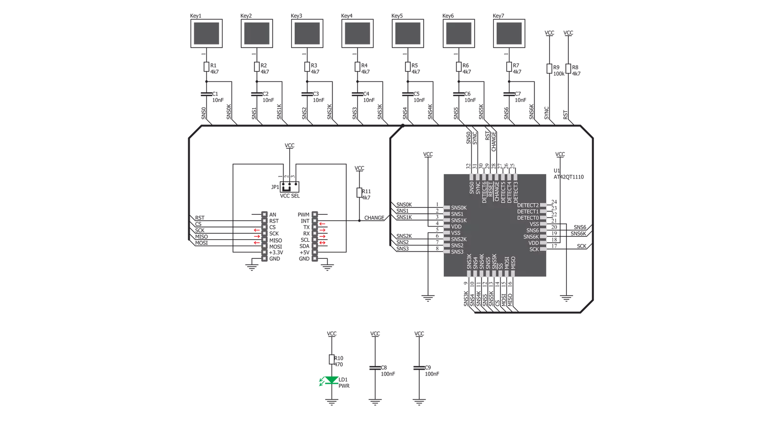
TouchKey 3 Click uses the AT42QT1110, an 11-key QTouch® Touch Sensor IC from Microchip. It can be configured in several different ways, depending on the application: it can be used to support more or less sensor channels, to support direct outputs for an interrupt triggering on a specific channel, to have its #CHANGE output pin used for triggering one global interrupt whenever one of the sensors detects a touch event, or to improve the power consumption by employing the SYNC input signal for triggering sensing bursts in specific time intervals. TouchKey 3 Click uses seven capacitive sensing channels, with the #CHANGE pin routed to the INT pin of the mikroBUS™, so that an interrupt can be triggered if any of the sensors detect a touch event, for example. This can trigger an SPI read cycle only when the key is pressed, avoiding the need for constant polling of the AT42QT1110’s registers. However, the behavior of the #CHANGE pin is programmable and more information about its functionality can be found in the AT42QT1110 datasheet. The SYNC pin is pulled high and not used, allowing the click board™ to run in the Free Run mode, which enables the fastest key press detection times. #RESET pin of the AT42QT1110 is routed to the RST pin of the mikroBUS™, and it is used to reset the device and reinitialize its working parameters - either with values stored in the EEPROM or the default values that are loaded into the RAM, in case the EEPROM does not contain any saved values. SPI will not be available for 160ms after the RESET event has occurred. This pin should be pulled to a HIGH logic level to reset the device. The AT42QT1110 sensor has internal registers that are used for configuring
the working parameters of the device. The device Mode register is one of the important config registers, and it is used to control the overall operation of the click board™. Bit KEY_AC of the Device Mode register is used to set the detection triggering mode: 0 by SYNC pin or 1 by internal timer (should be set to 1, since the SYNC pin is pulled to a HIGH logic level); MODE bit: 0 for 7, or 1 for 11 channels configuration (should be set to 0 for 7 channels operation); SIGNAL bit: 0 for serial, or 1 for parallel; SYNC bit: 0 for rising edge, or 1 for zero level detect (disregarded, since the KEY_AC is set to 1); REPEAT TIME bit field: these four bits set the repeat time between the scanning intervals. If the REPEAT TIME is set to 0, the new scanning cycle will be performed immediately after the previous cycle, allowing for the fastest touch detection. The value of this bitfield is multiplied by 16ms to get the final repeat time. TouchKey 3 click also features signal processing to provide better button detection. Adjacent Key Suppression (AKS®) technology can be configured on each channel. A group of channels with the AKS® enabled will be processed so that only the detected key remains active, while other sensors will be disregarded. The other sensors with the AKS® enabled will be activated only when the currently active key is released. The sensor channels for which AKS® is not selected will retain the ability to sense touch simultaneously. This technology allows better key accuracy and less false detections in applications requiring key press detection precision. Detection Integration (DI) is another technology used to sense the key press better. When the button is first pressed, a counter is started. If the counter expires
and the sensor channel still detects a key press, that keypress will be declared true. Else it will be disregarded as false. This serves as a kind of debouncing and prevents false detections. DI technology is implemented per sensor. The AT42QT1110 IC has EEPROM memory, which can store current RAM settings. All the registers are kept in RAM, and after the power-on reset event (POR), the values stored in the EEPROM memory will be automatically copied to the registers. Else, the registers will be loaded with the default values. All these functions can be accessed and configured via the SPI bus. The SPI communication can be either in Quick SPI mode or full SPI mode. While working in the Quick SPI mode, the device will send a sequence of 7 bytes containing the essential data, such as the detection and error status of the channels. In this mode, no-host MCU commands are required, and this sequence will be clocked out continuously from the AT42QT1110 IC. Quick SPI mode is enabled by setting the SPI_EN bit in the Comms Options setup register. All the SPI pins and the chip select pin are routed to the appropriate pins on the mikroBUS™. Onboard SMD jumper labeled VCC SEL selects the power supply and logic voltage level. This click board can work with both 3.3V and 5V MCUs. The provided TouchKey 3 Click library contains functions used to configure the device and read touch events comprehensively and intuitively. The included example application demonstrates the usage of these functions, and it can be used as a reference for a custom design.


Features overview
Development board
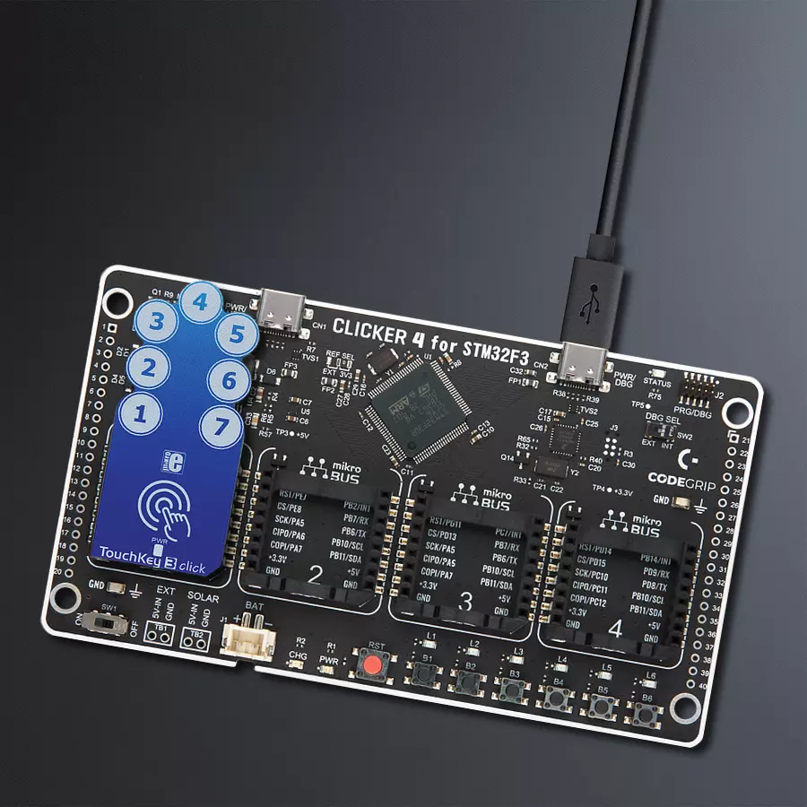
Clicker 4 for STM32F3 is a compact development board designed as a complete solution, you can use it to quickly build your own gadgets with unique functionalities. Featuring a STM32F302VCT6, four mikroBUS™ sockets for Click boards™ connectivity, power managment, and more, it represents a perfect solution for the rapid development of many different types of applications. At its core, there is a STM32F302VCT6 MCU, a powerful microcontroller by STMicroelectronics, based on the high-
performance Arm® Cortex®-M4 32-bit processor core operating at up to 168 MHz frequency. It provides sufficient processing power for the most demanding tasks, allowing Clicker 4 to adapt to any specific application requirements. Besides two 1x20 pin headers, four improved mikroBUS™ sockets represent the most distinctive connectivity feature, allowing access to a huge base of Click boards™, growing on a daily basis. Each section of Clicker 4 is clearly marked, offering an intuitive and clean interface. This makes working with the development
board much simpler and thus, faster. The usability of Clicker 4 doesn’t end with its ability to accelerate the prototyping and application development stages: it is designed as a complete solution which can be implemented directly into any project, with no additional hardware modifications required. Four mounting holes [4.2mm/0.165”] at all four corners allow simple installation by using mounting screws. For most applications, a nice stylish casing is all that is needed to turn the Clicker 4 development board into a fully functional, custom design.

Microcontroller Overview
MCU Card / MCU

Architecture
ARM Cortex-M4
MCU Memory (KB)
256
Silicon Vendor
STMicroelectronics
Pin count
100
RAM (Bytes)
40960
Used MCU Pins
mikroBUS™ mapper
Take a closer look
Click board™ Schematic
Step by step
Project assembly

Start by selecting your development board and Click board™. Begin with the CLICKER 4 for STM32F302VCT6 as your development board.


Software Support
Library Description
This library contains API for TouchKey 3 Click driver.
Key functions:
touchkey3_send_command- This function executes one of the possible commandstouchkey3_send_request- This function sends a request command, and returns the responsetouchkey3_get_data- This function reads from a selected configuration register
Open Source
Code example
The complete application code and a ready-to-use project are available through the NECTO Studio Package Manager for direct installation in the NECTO Studio. The application code can also be found on the MIKROE GitHub account.
/*!
 * \file
 * \brief TouchKey3 Click example
 *
 * # Description
 * This Click uses 7 capacitive sensing channels, with the #CHANGE pin routed to the INT pin of the mikroBUS™,
 * so that an interrupt can be triggered if any of the sensors detect a touch event.
 * This can be used to trigger an SPI read cycle only when the key is actually pressed,
 * avoiding the need for constant polling of the sensor registers.
 *
 * The demo application is composed of two sections :
 *
 * ## Application Init
 * Initializes Click driver and performs a soft reset of the Click.
 *
 * ## Application Task
 * Reads the status of the keys, and outputs a message if a key is touched.
 *
 *
 * \author MikroE Team
 *
 */
// ------------------------------------------------------------------- INCLUDES

#include "board.h"
#include "log.h"
#include "touchkey3.h"


// ------------------------------------------------------------------ VARIABLES

static touchkey3_t touchkey3;
static log_t logger;

static uint8_t return_data[ 2 ];
static uint8_t counter;
static uint8_t temp;
static uint8_t old_state;
static const uint16_t timeout_state = 1000;
static uint16_t timeout_cnt;

// ------------------------------------------------------ APPLICATION FUNCTIONS

uint8_t calculationt_index ( uint8_t data_in )
{
    uint8_t counter = 2;

    if ( data_in <= 2 )
    {
        return data_in;
    }

    while ( data_in > 2 )
    {
        data_in /= 2;
        counter++;
    }

    return counter;
}

void application_init ( void )
{
    log_cfg_t log_cfg;
    touchkey3_cfg_t cfg;

    /**
     * Logger initialization.
     * Default baud rate: 115200
     * Default log level: LOG_LEVEL_DEBUG
     * @note If USB_UART_RX and USB_UART_TX
     * are defined as HAL_PIN_NC, you will
     * need to define them manually for log to work.
     * See @b LOG_MAP_USB_UART macro definition for detailed explanation.
     */
    LOG_MAP_USB_UART( log_cfg );
    log_init( &logger, &log_cfg );
    log_info( &logger, "---- Application Init ----" );

    //  Click initialization.

    touchkey3_cfg_setup( &cfg );
    TOUCHKEY3_MAP_MIKROBUS( cfg, MIKROBUS_1 );
    touchkey3_init( &touchkey3, &cfg );

    touchkey3_reset( &touchkey3 );
    touchkey3_send_command( &touchkey3, TOUCHKEY3_CMD_RESET );
    timeout_cnt = timeout_state;

    Delay_ms ( 300 );
}

void application_task ( void )
{
    touchkey3_send_request( &touchkey3, TOUCHKEY3_REQ_ALL_KEYS, &return_data );

    for ( counter = 0; counter < 7; counter++ )
    {
        if ( ( return_data[ 1 ] >> counter ) & 0x01 )
        {
            log_printf( &logger, "Touch detected on key %d\r\n", ( uint16_t )(counter+1) );
            Delay_ms ( 1000 );
        }
    }
}

int main ( void )
{
    /* Do not remove this line or clock might not be set correctly. */
    #ifdef PREINIT_SUPPORTED
    preinit();
    #endif

    application_init( );

    for ( ; ; )
    {
        application_task( );
    }

    return 0;
}


// ------------------------------------------------------------------------ END
Additional Support
Resources
Category:Capacitive


