Adjust various settings with just a single touch thanks to the IQS333 and PIC32MZ2048EFM100
Glide into the future

Published Jul 22, 2025
Click board™
Cap Slider 2 Click
Dev. board
Curiosity PIC32 MZ EF
Compiler
NECTO Studio
MCU
PIC32MZ2048EFM100
Integrate capacitive slider functionalities into your applications and craft immersive experiences that captivate the senses
A
A
Hardware Overview
How does it work?
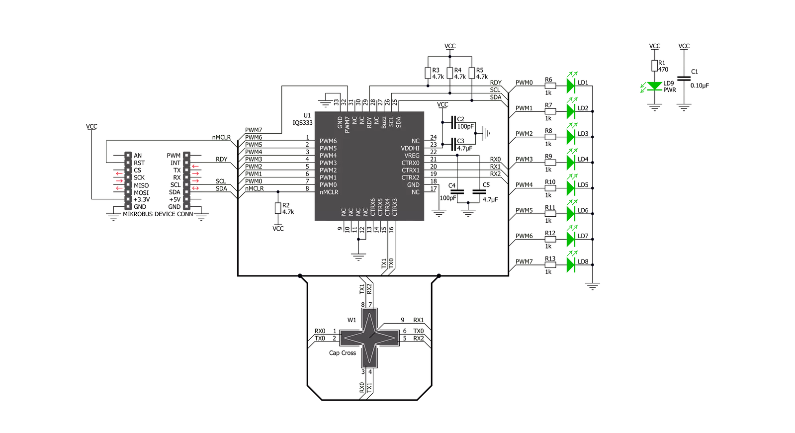
CAP Slider 2 Click is based on the IQS333, ProxSense® IC, a 9-channel projected (or 7-channel self) capacitive proximity and touch controller from Azoteq. This IC has advanced features such as auto drift compensation, Long proximity range, Automatic adjustment for optimal performance (ATI), two Configurable 11-bit sliders/scroll Slider 2s, and more. These features enable CAP Slider 2 Click to exhibit reliable and accurate touch detection. Capacitive touch sensing is based on detecting a change in capacitance due to the influence of a foreign object. The capacitance of the sensor, also known as the antenna, is measured and monitored, and if a significant change occurs after processing by the
detection integrator, a touch event is acknowledged. CAP Slider 2 Click is designed with these requirements, and electrodes are „Projected XY-cross slider“ shaped. CAP Slider 2 click also contains 8 LEDs whose function can be user-defined. LEDs are connected to PWM LED driver pins on IQS333, so the user can turn LEDs on or off and control illumination using the dimming modes that IQS333 supports. The IQS333 IC interfaces to a master controller via a 3-wire (SDA, SCL, and RDY) serial interface bus that is I2C™ compatible, with a maximum communication speed of 400kbit/s. The host MCU can force communication anytime by pulling the RDY line low. The communication will start directly
following the current conversion cycle. If the watchdog timer terminates the event, the device will reset. After every power-on cycle, the device will recalibrate itself. It will take some time, so it should be considered when building custom applications. MikroElektronika provides libraries and the demo application to be used as a reference for future designs. As mentioned, this Click board™ is I2C™ compatible and uses SCL, SDA, and RDY pins for communication routed to SCL, SDA, and INT pins on mikroBUS™, respectively. Besides that, a CLR pin is available on board which is routed to the RST pin on mikroBUS™ and used to master reset the IC.


Features overview
Development board
Curiosity PIC32 MZ EF development board is a fully integrated 32-bit development platform featuring the high-performance PIC32MZ EF Series (PIC32MZ2048EFM) that has a 2MB Flash, 512KB RAM, integrated FPU, Crypto accelerator, and excellent connectivity options. It includes an integrated programmer and debugger, requiring no additional hardware. Users can expand
functionality through MIKROE mikroBUS™ Click™ adapter boards, add Ethernet connectivity with the Microchip PHY daughter board, add WiFi connectivity capability using the Microchip expansions boards, and add audio input and output capability with Microchip audio daughter boards. These boards are fully integrated into PIC32’s powerful software framework, MPLAB Harmony,
which provides a flexible and modular interface to application development a rich set of inter-operable software stacks (TCP-IP, USB), and easy-to-use features. The Curiosity PIC32 MZ EF development board offers expansion capabilities making it an excellent choice for a rapid prototyping board in Connectivity, IOT, and general-purpose applications.

Microcontroller Overview
MCU Card / MCU

Architecture
PIC32
MCU Memory (KB)
2048
Silicon Vendor
Microchip
Pin count
100
RAM (Bytes)
524288
Used MCU Pins
mikroBUS™ mapper
Take a closer look
Click board™ Schematic
Step by step
Project assembly

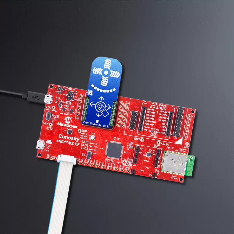
Start by selecting your development board and Click board™. Begin with the Curiosity PIC32 MZ EF as your development board.


Software Support
Library Description
This library contains API for Cap Slider 2 Click driver.
Key functions:
capsldr2_write_reg- Generic Write functioncapsldr2_read_reg- Generic Read functioncapsldr2_check_data_ready- Data Ready Check function
Open Source
Code example
The complete application code and a ready-to-use project are available through the NECTO Studio Package Manager for direct installation in the NECTO Studio. The application code can also be found on the MIKROE GitHub account.
/*!
 * \file
 * \brief CapSlider2 Click example
 *
 * # Description
 * This application could be used for controlling various devices.
 *
 * The demo application is composed of two sections :
 *
 * ## Application Init
 * Initializes I2C interface, performs the device reset and configurations
 * and sets the desired threshold value which determines sensor sensitivity.
 *
 * ## Application Task
 * Checks for data ready and then read capacitance from all channels.
 * There are two sliders on the clik board (X and Y).
 * X slider selects which LEDs are being activated,
 * while Y slider increases/decreases the LEDs intensity.
 *
 * ## NOTE
 * In some cases, the user will need to wait several seconds after the Click initialization
 * for the sensor to be stabilized.
 *
 * \author MikroE Team
 *
 */
// ------------------------------------------------------------------- INCLUDES

#include "board.h"
#include "log.h"
#include "capslider2.h"

// ------------------------------------------------------------------ VARIABLES

static capslider2_t capslider2;
static log_t logger;

// ------------------------------------------------------ APPLICATION FUNCTIONS

uint32_t wheel_avrg1;
uint32_t wheel_avrg2;
uint16_t out_val;
uint8_t out_mode;
uint8_t cnt;

void horizontal_check(  )
{
    out_val = ((wheel_avrg1 / cnt) / 142.1) - 5;
    out_mode = CAPSLDR2_LED_NUMBER;
}

void vertical_check(  )
{
    out_val = (2047 - (wheel_avrg1 / cnt)) / 147.4;
    out_mode = CAPSLDR2_LED_INTENSITY;
}


void application_init ( void )
{
    log_cfg_t log_cfg;
    capslider2_cfg_t cfg;

    /**
     * Logger initialization.
     * Default baud rate: 115200
     * Default log level: LOG_LEVEL_DEBUG
     * @note If USB_UART_RX and USB_UART_TX
     * are defined as HAL_PIN_NC, you will
     * need to define them manually for log to work.
     * See @b LOG_MAP_USB_UART macro definition for detailed explanation.
     */
    LOG_MAP_USB_UART( log_cfg );
    log_init( &logger, &log_cfg );
    log_info( &logger, "---- Application Init ----" );

    //  Click initialization.

    capslider2_cfg_setup( &cfg );
    CAPSLIDER2_MAP_MIKROBUS( cfg, MIKROBUS_1 );
    capslider2_init( &capslider2, &cfg );

    Delay_ms ( 500 );

    cnt = 0;
    wheel_avrg1 = 0;
    wheel_avrg2 = 0;

    capsldr2_reset( &capslider2 );
    Delay_ms ( 500 );

    capsldr2_enable_chann( &capslider2, CAPSLDR2_CH0_PROX_EN | CAPSLDR2_CH1_EN | CAPSLDR2_CH2_EN | CAPSLDR2_CH3_EN | CAPSLDR2_CH4_EN | CAPSLDR2_CH5_EN | CAPSLDR2_CH6_EN | CAPSLDR2_CH7_EN | CAPSLDR2_CH8_EN | CAPSLDR2_CH9_EN );
    capsldr2_config( &capslider2 );
    capsldr2_set_threshold( &capslider2, 0x04 );
    Delay_ms ( 1000 );
    Delay_ms ( 1000 );
    Delay_ms ( 1000 );
    Delay_ms ( 1000 );

    log_printf( &logger, "CAP Slider 2 is initialized\r\n" );

}

void application_task ( void )
{
    uint16_t data_wheel1;
    uint16_t data_wheel2;
    uint8_t ready_check;

    ready_check = capsldr2_check_data_ready( &capslider2 );

    if (ready_check == CAPSLDR2_DATA_READY)
    {
        capsldr2_get_data( &capslider2, &data_wheel1, &data_wheel2 );

        wheel_avrg1 += data_wheel1;
        wheel_avrg2 += data_wheel2;
        cnt++;
    }

    if (cnt == 1)
    {
        if ((wheel_avrg2 / cnt) > 1800)
        {
            horizontal_check(  );
            capsldr2_set_output( &capslider2, out_val, out_mode );
        }
        else if (((wheel_avrg2 / cnt) < 1650) && ((wheel_avrg2 / cnt) > 1000))
        {
            vertical_check(  );
            capsldr2_set_output( &capslider2, out_val, out_mode );
        }

        wheel_avrg1 = 0;
        wheel_avrg2 = 0;
        cnt = 0;
    }
}

int main ( void )
{
    /* Do not remove this line or clock might not be set correctly. */
    #ifdef PREINIT_SUPPORTED
    preinit();
    #endif

    application_init( );

    for ( ; ; )
    {
        application_task( );
    }

    return 0;
}


// ------------------------------------------------------------------------ END
Additional Support
Resources
Category:Capacitive


