Provide an intuitive and reliable touch interface with AT42QT1010 and STM32F031K6
Vivify the environment with your touch

Published Oct 01, 2024
Click board™
Cap Touch Click
Dev. board
Nucleo 32 with STM32F031K6 MCU
Compiler
NECTO Studio
MCU
STM32F031K6
Designed for precision and efficiency, our capacitive touchkey solution offers seamless integration into various applications, enabling users to experience smooth and responsive touch interactions
A
A
Hardware Overview
How does it work?
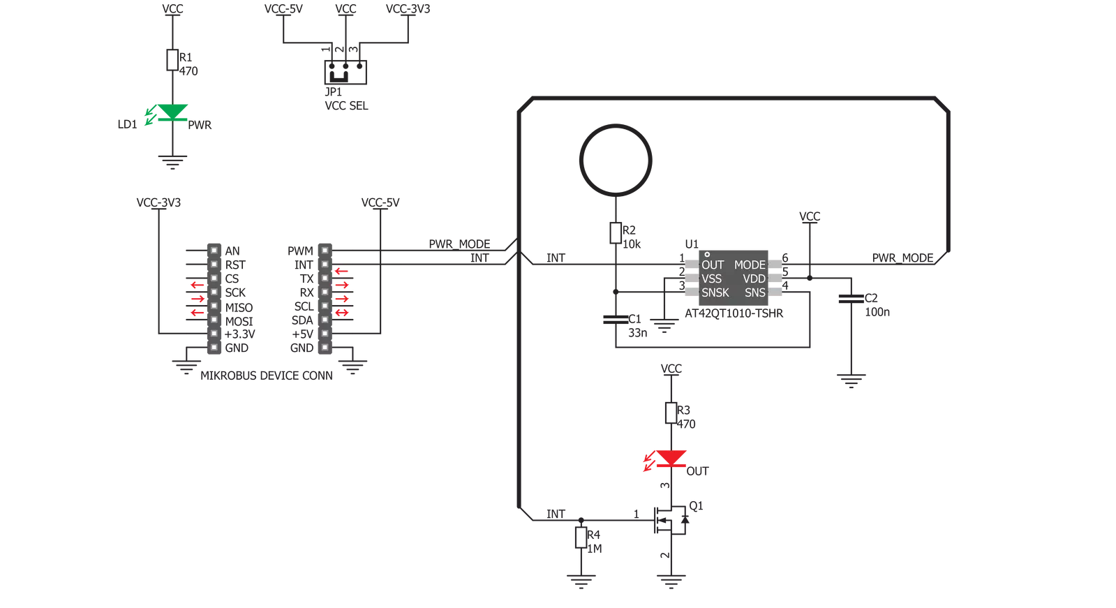
Cap Touch Click is based on the AT42QT1010, a single-key QTouch® touch sensor IC from Microchip. This IC has advanced features such as self-calibration, auto drift compensation, noise filtering, and proprietary QTouch® technology based on the patented charge-transfer method. These features enable Cap Touch Click to exhibit reliable and accurate touch detection. Capacitive touch sensing is based on detecting a change in capacitance due to the influence of a foreign object. The capacitance of the sensor, also known as the antenna, is measured and monitored. A touch event is acknowledged if a significant change occurs after processing by the detection integrator. Cap Touch Click is designed with these requirements in mind, so it can successfully detect a touch. This IC uses short bursts to monitor the capacitance, and it features three modes of operation: Fast mode, Low Power mode, and SYNC mode. Switching between Fast and Low Power modes is done by pulling the SYNC/MODE pin, routed to the mikroBUS™ PWM pin, to a HIGH or LOW logic level, respectively. Fast mode yields the fastest detection time, yet it uses the most power, as the device continuously sends measuring
bursts, with about 1ms of delay between them. The device will work in this mode if the PWM pin stays permanently at the HIGH logic level. Low Power mode will send measurement bursts with about 80mS delay in between, significantly lowering the power consumption, as well as the responsiveness of the device. However, when a touch is detected, the device will enter the Fast mode again, allowing the detection integration to detect a valid touch event. The device will work in Low Power mode if the PWM pin stays at the LOW logic level permanently. SYNC mode controls the measurement burst timing by the clock signal provided on the PWM pin. It reduces crosstalk when using more devices or enhances noise immunity from low-frequency sources, such as 50Hz or 60Hz mains signals. The device's output is routed to the INT pin of the mikroBUS™. The output pin is active high - on a valid detection, it will be set to a HIGH logic level. The output will stay at the HIGH level as long as the touch event is active (touch hold) and will be terminated by the Max On duration feature - a timer set to about 60 seconds. The device will be recalibrated if the Max On duration feature terminates the event.
The Max On duration feature normally resolves issues when the button detects an event for too long. If an object obstructs the sensor pad, e.g., when adding a protective plastic layer, this feature will recalibrate the sensor to accommodate this plastic layer. After every power-on cycle, the device will recalibrate itself. It will take some time, so it should be considered when building custom applications. MIKROE provides libraries and the demo application that can be used as a reference for future designs. The output of this device is too weak to drive a LED. Yet, a touch button is only good with the LED or other indication of its state. Cap Touch Click is equipped with the N-type MOSFET transistor to drive a LED, which is activated by the output pin of the AT42QT1010 IC. It can drive one red LED without a problem. The onboard SMD jumper labeled VCC SEL is used to select the operating voltage of the device. It is capable of working with both 3.3V and 5V capable MCUs. Besides the PWM pin, used for mode selection, and the INT pin, used to signal the button state to the MCU, no other lines of the mikroBUS™ are used.


Features overview
Development board
Nucleo 32 with STM32F031K6 MCU board provides an affordable and flexible platform for experimenting with STM32 microcontrollers in 32-pin packages. Featuring Arduino™ Nano connectivity, it allows easy expansion with specialized shields, while being mbed-enabled for seamless integration with online resources. The
board includes an on-board ST-LINK/V2-1 debugger/programmer, supporting USB reenumeration with three interfaces: Virtual Com port, mass storage, and debug port. It offers a flexible power supply through either USB VBUS or an external source. Additionally, it includes three LEDs (LD1 for USB communication, LD2 for power,
and LD3 as a user LED) and a reset push button. The STM32 Nucleo-32 board is supported by various Integrated Development Environments (IDEs) such as IAR™, Keil®, and GCC-based IDEs like AC6 SW4STM32, making it a versatile tool for developers.

Microcontroller Overview
MCU Card / MCU

Architecture
ARM Cortex-M0
MCU Memory (KB)
32
Silicon Vendor
STMicroelectronics
Pin count
32
RAM (Bytes)
4096
You complete me!
Accessories
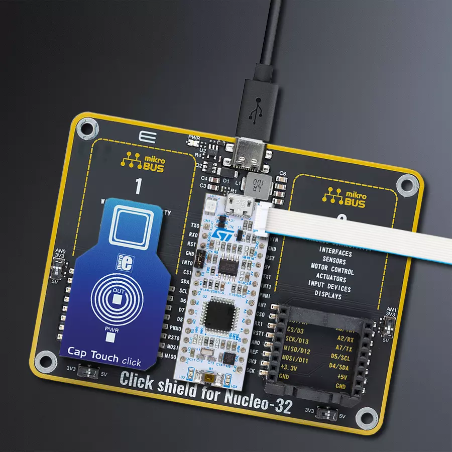
Click Shield for Nucleo-32 is the perfect way to expand your development board's functionalities with STM32 Nucleo-32 pinout. The Click Shield for Nucleo-32 provides two mikroBUS™ sockets to add any functionality from our ever-growing range of Click boards™. We are fully stocked with everything, from sensors and WiFi transceivers to motor control and audio amplifiers. The Click Shield for Nucleo-32 is compatible with the STM32 Nucleo-32 board, providing an affordable and flexible way for users to try out new ideas and quickly create prototypes with any STM32 microcontrollers, choosing from the various combinations of performance, power consumption, and features. The STM32 Nucleo-32 boards do not require any separate probe as they integrate the ST-LINK/V2-1 debugger/programmer and come with the STM32 comprehensive software HAL library and various packaged software examples. This development platform provides users with an effortless and common way to combine the STM32 Nucleo-32 footprint compatible board with their favorite Click boards™ in their upcoming projects.

Used MCU Pins
mikroBUS™ mapper
Take a closer look
Click board™ Schematic
Step by step
Project assembly

Start by selecting your development board and Click board™. Begin with the Nucleo 32 with STM32F031K6 MCU as your development board.


Software Support
Library Description
This library contains API for Cap Touch Click driver.
Key functions:
captouch_set_mode- Mode selection functioncaptouch_get_touch- Get touch state function
Open Source
Code example
The complete application code and a ready-to-use project are available through the NECTO Studio Package Manager for direct installation in the NECTO Studio. The application code can also be found on the MIKROE GitHub account.
/*!
 * \file
 * \brief Cap Touch Click example
 *
 * # Description
 * Demo application is used to shows basic controls Cap Touch Click.
 *
 * The demo application is composed of two sections :
 *
 * ## Application Init
 * Configuring Clicks and log objects.
 * Settings the Click in the default configuration.
 *
 * ## Application Task
 *  Checks for a new touch event. If so, prints the message to USBUART.
 *
 * \author Katarina Perendic
 *
 */
// ------------------------------------------------------------------- INCLUDES

#include "board.h"
#include "log.h"
#include "captouch.h"

// ------------------------------------------------------------------ VARIABLES

static captouch_t captouch;
static log_t logger;
// ------------------------------------------------------ APPLICATION FUNCTIONS

void application_init ( void )
{
    log_cfg_t log_cfg;
    captouch_cfg_t cfg;

    /**
     * Logger initialization.
     * Default baud rate: 115200
     * Default log level: LOG_LEVEL_DEBUG
     * @note If USB_UART_RX and USB_UART_TX
     * are defined as HAL_PIN_NC, you will
     * need to define them manually for log to work.
     * See @b LOG_MAP_USB_UART macro definition for detailed explanation.
     */
    LOG_MAP_USB_UART( log_cfg );
    log_init( &logger, &log_cfg );
    log_info( &logger, "---- Application Init ----" );

    //  Click initialization.

    captouch_cfg_setup( &cfg );
    CAPTOUCH_MAP_MIKROBUS( cfg, MIKROBUS_1 );
    captouch_init( &captouch, &cfg );

    captouch_default_cfg( &captouch );
}

void application_task ( void )
{
    uint8_t touch;

    //  Task implementation.

    touch = captouch_get_touch( &captouch );
    if ( touch != 0 )
    {
        log_printf( &logger, "-- New Touch\r\n" );
        Delay_ms ( 200 );
    }
}

int main ( void )
{
    /* Do not remove this line or clock might not be set correctly. */
    #ifdef PREINIT_SUPPORTED
    preinit();
    #endif

    application_init( );

    for ( ; ; )
    {
        application_task( );
    }

    return 0;
}


// ------------------------------------------------------------------------ END
Additional Support
Resources
Category:Capacitive


