Achieve dependable power source selection and management with LTC4417 and STM32F031K6
Intelligent power multiplexing solution for high-availability systems

Published Aug 05, 2025
Click board™
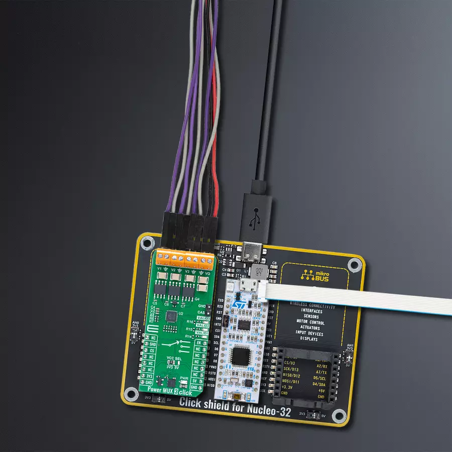
Power MUX 3 Click
Dev. board
Nucleo 32 with STM32F031K6 MCU
Compiler
NECTO Studio
MCU
STM32F031K6
Gain prioritized switching between multiple power sources for uninterrupted and reliable system operation
A
A
Hardware Overview
How does it work?
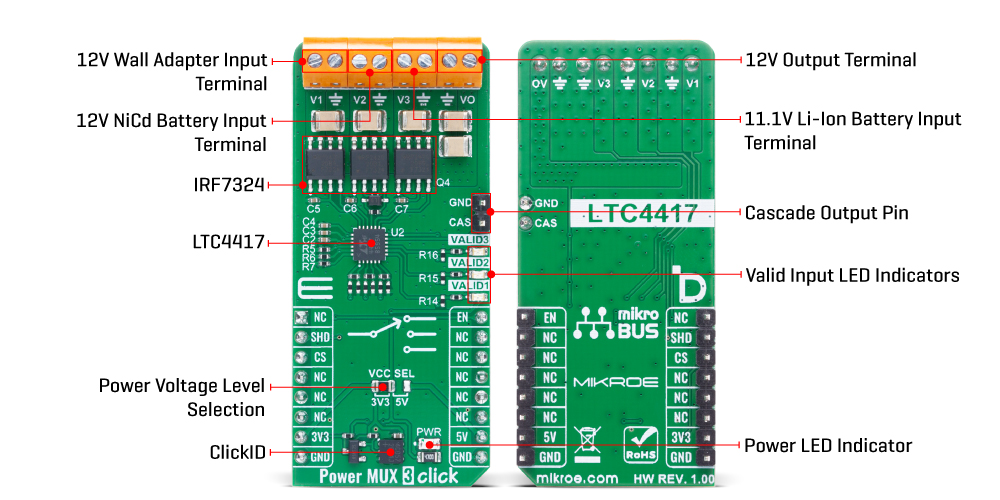
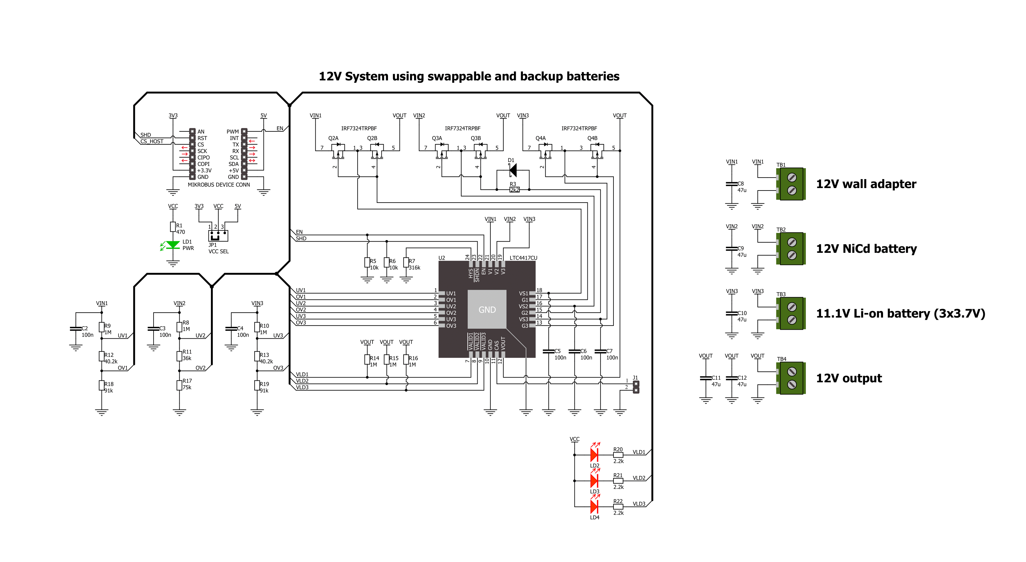
Power MUX 3 Click is based on the LTC4417, a prioritized PowerPath™ controller from Analog Devices that autonomously selects and connects one of up to three valid power sources to a common output (VO terminal) based on a predefined priority. The board represents a 12V system setup using a swappable and backup battery configuration, where V1 is typically connected to a 12V wall adapter, V2 to a NiCd battery supply, and V3 to a Li-Ion battery supply. The priority of the sources is hardwired, with V1 being the highest and V3 the lowest. The Power MUX 3 Click is designed to manage multiple power sources in systems requiring high availability and controlled power switching, such as industrial handheld instruments, battery backup systems, and computer peripherals. A power source is considered valid if its voltage remains continuously within the undervoltage (UV) and overvoltage (OV) limits for at least 256 milliseconds. As soon as the
currently connected highest-priority valid input falls outside of this window, the LTC4417 automatically disconnects it and connects the next highest-priority input that meets the UV/OV criteria. This ensures uninterrupted and reliable power delivery without manual intervention. Power MUX 3 Click uses only two control pins from the mikroBUS™ socket: EN and SHD. The EN (Enable) pin allows the user to swiftly connect or disconnect channels without resetting the UV/OV validation timers, while the SHD (Shutdown) pin forces the LTC4417 into a low-power mode and resets all 256ms timers for each channel, effectively restarting the validation process. The board also supports cascading of two or more Power MUX 3 Clicks via the CAS pin, enabling the creation of advanced power path management topologies with more than three inputs. The LTC4417 integrates fast non-overlap switching logic to prevent both reverse conduction and cross conduction during transitions, thereby
minimizing output droop and ensuring safe switching. It features a 6V gate clamp to protect external MOSFETs (such as the onboard IRF7324 MOSFETs), and a controlled output ramp function that suppresses inrush currents at power-up. Additionally, each input has an open-drain VALID LED indicator which lights up red to signify that the respective input has been continuously valid for at least 256ms, providing immediate visual feedback on power source health and readiness. This Click board™ can operate with either 3.3V or 5V logic voltage levels selected via the VCC SEL jumper. This way, both 3.3V and 5V capable MCUs can use the communication lines properly. Also, this Click board™ comes equipped with a library containing easy-to-use functions and an example code that can be used as a reference for further development.
Features overview
Development board
Nucleo 32 with STM32F031K6 MCU board provides an affordable and flexible platform for experimenting with STM32 microcontrollers in 32-pin packages. Featuring Arduino™ Nano connectivity, it allows easy expansion with specialized shields, while being mbed-enabled for seamless integration with online resources. The
board includes an on-board ST-LINK/V2-1 debugger/programmer, supporting USB reenumeration with three interfaces: Virtual Com port, mass storage, and debug port. It offers a flexible power supply through either USB VBUS or an external source. Additionally, it includes three LEDs (LD1 for USB communication, LD2 for power,
and LD3 as a user LED) and a reset push button. The STM32 Nucleo-32 board is supported by various Integrated Development Environments (IDEs) such as IAR™, Keil®, and GCC-based IDEs like AC6 SW4STM32, making it a versatile tool for developers.

Microcontroller Overview
MCU Card / MCU

Architecture
ARM Cortex-M0
MCU Memory (KB)
32
Silicon Vendor
STMicroelectronics
Pin count
32
RAM (Bytes)
4096
You complete me!
Accessories
Click Shield for Nucleo-32 is the perfect way to expand your development board's functionalities with STM32 Nucleo-32 pinout. The Click Shield for Nucleo-32 provides two mikroBUS™ sockets to add any functionality from our ever-growing range of Click boards™. We are fully stocked with everything, from sensors and WiFi transceivers to motor control and audio amplifiers. The Click Shield for Nucleo-32 is compatible with the STM32 Nucleo-32 board, providing an affordable and flexible way for users to try out new ideas and quickly create prototypes with any STM32 microcontrollers, choosing from the various combinations of performance, power consumption, and features. The STM32 Nucleo-32 boards do not require any separate probe as they integrate the ST-LINK/V2-1 debugger/programmer and come with the STM32 comprehensive software HAL library and various packaged software examples. This development platform provides users with an effortless and common way to combine the STM32 Nucleo-32 footprint compatible board with their favorite Click boards™ in their upcoming projects.

Used MCU Pins
mikroBUS™ mapper
Take a closer look
Click board™ Schematic
Step by step
Project assembly

Start by selecting your development board and Click board™. Begin with the Nucleo 32 with STM32F031K6 MCU as your development board.


Software Support
Library Description
Power MUX 3 Click demo application is developed using the NECTO Studio, ensuring compatibility with mikroSDK's open-source libraries and tools. Designed for plug-and-play implementation and testing, the demo is fully compatible with all development, starter, and mikromedia boards featuring a mikroBUS™ socket.
Example Description
This example demonstrates the use of the Power MUX 3 Click board. It enables automatic selection between three power sources, selecting the highest voltage as the input source. The demo toggles the output ON and OFF at regular intervals, allowing observation of the output control functionality.
Key functions:
powermux3_cfg_setup- This function initializes Click configuration structure to initial values.powermux3_init- This function initializes all necessary pins and peripherals used for this Click board.powermux3_enable_device- This function enables the device by setting the SHD pin to HIGH on the Power MUX 3 Click board.powermux3_disable_device- This function disables the device by setting the SHD pin to LOW on the Power MUX 3 Click board.powermux3_enable_output- This function enables the output by setting the EN pin to HIGH on the Power MUX 3 Click board.powermux3_disable_output- This function disables the output by setting the EN pin to LOW on the Power MUX 3 Click board.
Application Init
Initializes the logger and the Power MUX 3 Click driver, then enables the device.
Application Task
Alternates enabling and disabling the output in 5-second intervals while logging the status.
Open Source
Code example
The complete application code and a ready-to-use project are available through the NECTO Studio Package Manager for direct installation in the NECTO Studio. The application code can also be found on the MIKROE GitHub account.
/*!
 * @file main.c
 * @brief Power MUX 3 Click Example.
 *
 * # Description
 * This example demonstrates the use of the Power MUX 3 Click board. It enables automatic
 * selection between three power sources, selecting the highest voltage as the input source.
 * The demo toggles the output ON and OFF at regular intervals, allowing observation of
 * the output control functionality.
 *
 * The demo application is composed of two sections:
 *
 * ## Application Init
 * Initializes the logger and the Power MUX 3 Click driver, then enables the device.
 *
 * ## Application Task
 * Alternates enabling and disabling the output in 5-second intervals while logging the status.
 *
 * @author Stefan Filipovic
 *
 */

#include "board.h"
#include "log.h"
#include "powermux3.h"

static powermux3_t powermux3;   /**< Power MUX 3 Click driver object. */
static log_t logger;    /**< Logger object. */

void application_init ( void )
{
    log_cfg_t log_cfg;  /**< Logger config object. */
    powermux3_cfg_t powermux3_cfg;  /**< Click config object. */

    /**
     * Logger initialization.
     * Default baud rate: 115200
     * Default log level: LOG_LEVEL_DEBUG
     * @note If USB_UART_RX and USB_UART_TX
     * are defined as HAL_PIN_NC, you will
     * need to define them manually for log to work.
     * See @b LOG_MAP_USB_UART macro definition for detailed explanation.
     */
    LOG_MAP_USB_UART( log_cfg );
    log_init( &logger, &log_cfg );
    log_info( &logger, " Application Init " );

    // Click initialization.
    powermux3_cfg_setup( &powermux3_cfg );
    POWERMUX3_MAP_MIKROBUS( powermux3_cfg, MIKROBUS_1 );
    if ( DIGITAL_OUT_UNSUPPORTED_PIN == powermux3_init( &powermux3, &powermux3_cfg ) )
    {
        log_error( &logger, " Communication init." );
        for ( ; ; );
    }

    powermux3_enable_device ( &powermux3 );

    log_info( &logger, " Application Task " );
}

void application_task ( void )
{
    log_printf( &logger, " Output enabled\r\n\n" );
    powermux3_enable_output ( &powermux3 );
    Delay_ms ( 1000 );
    Delay_ms ( 1000 );
    Delay_ms ( 1000 );
    Delay_ms ( 1000 );
    Delay_ms ( 1000 );
    log_printf( &logger, " Output disabled\r\n\n" );
    powermux3_disable_output ( &powermux3 );
    Delay_ms ( 1000 );
    Delay_ms ( 1000 );
    Delay_ms ( 1000 );
    Delay_ms ( 1000 );
    Delay_ms ( 1000 );
}

int main ( void )
{
    /* Do not remove this line or clock might not be set correctly. */
    #ifdef PREINIT_SUPPORTED
    preinit();
    #endif

    application_init( );

    for ( ; ; )
    {
        application_task( );
    }

    return 0;
}

// ------------------------------------------------------------------------ END
Additional Support
Resources
Category:Power Switch


