Achieve resistive and inductive high-side load switching with VN9D5D20FN and MK64FN1M0VDC12
Intelligent, safe, and versatile high-side switching solution for automotive and industrial loads

Published Jul 30, 2025
Click board™
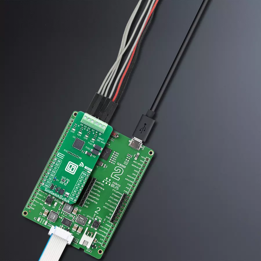
SolidSwitch 9 Click
Dev. board
Clicker 2 for Kinetis
Compiler
NECTO Studio
MCU
MK64FN1M0VDC12
Gain intelligent high-side switching control with diagnostics, PWM, and current sensing across four independent channels
A
A
Hardware Overview
How does it work?
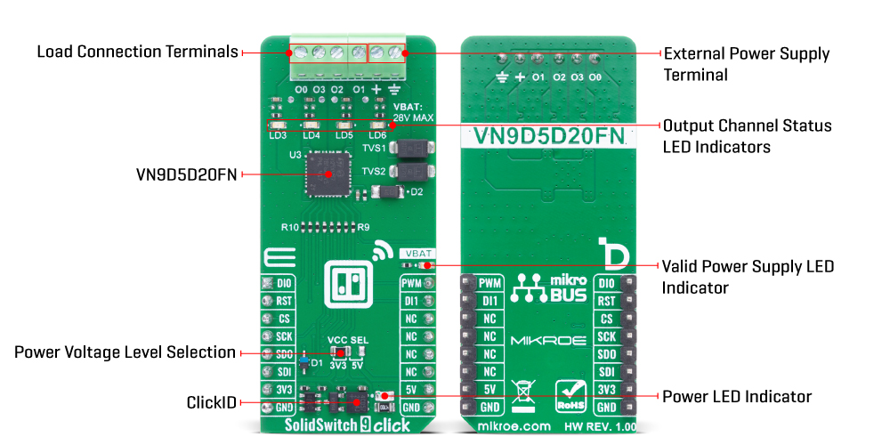
SolidSwitch 9 Click is based on the VN9D5D20FN, a 4-channel high-side driver with SPI control from STMicroelectronics, developed using advanced VIPower technology and qualified under the AEC-Q100 standard. This Click board™ provides high-side switching capabilities across four independent channels, designed to control both resistive and inductive loads directly connected to ground in automotive applications. Its compliance with the European directive 2002/95/EC ensures environmental compatibility. The core functionality is centered around a 24-bit SPI interface used for programming, diagnostics, and real-time control, offering precise digital current sensing feedback for each channel via an integrated 10-bit ADC with an accuracy of 0.1% of the full-scale range. For even more precision, trimming bits allow fine-tuning of the ADC reference current. The VN9D5D20FN features four output channels (O0 to O3), which can be controlled either via the SPI interface or through two user-assignable direct inputs (DI0 and DI1), enabling flexible control even in scenarios
where SPI is unavailable. Each output is accompanied by its own LED indicator (LD3 to LD6), allowing for immediate visual confirmation of the output state. To enhance safety and reliability, the VN9D5D20FN implements several diagnostic and protection mechanisms including open-load detection in the OFF-state, SPI-readable fault flags for conditions such as open-load, output short to VCC, overtemperature, communication errors, power limitations, and latch-off events. The output current is actively limited to prevent damage during overloads, and power dissipation is regulated through dynamic thermal management, with a programmable shutdown mechanism that can either latch or auto-restart after a defined period. A dedicated VBAT LED indicator on the board provides a clear visual cue for system power availability, supporting input voltages up to 28V. The VN9D5D20FN supports multiple operation modes including Reset, Fail-safe, Normal, Standby, Sleep mode 1, Sleep mode 2, and Battery undervoltage mode, where the Reset, Fail-safe,
and Sleep mode 1 are collectively referred to as limp-home mode. In this mode, the device can function independently of the SPI interface, using VBAT and DIx signals for mode transitions and output control. By default configuration, DI0 controls outputs O0 and O1, while DI1 manages O2 and O3. Additionally, the VN9D5D20FN integrates a powerful PWM engine capable of generating independent phase-shifted PWM signals for each channel, supporting four selectable divider ratios ranging from 1/512 to 1/4096, making it ideal for finely tuned load modulation or motor control applications. This Click board™ can operate with either 3.3V or 5V logic voltage levels selected via the VCC SEL jumper. This way, both 3.3V and 5V capable MCUs can use the communication lines properly. Also, this Click board™ comes equipped with a library containing easy-to-use functions and an example code that can be used as a reference for further development.
Features overview
Development board
Clicker 2 for Kinetis is a compact starter development board that brings the flexibility of add-on Click boards™ to your favorite microcontroller, making it a perfect starter kit for implementing your ideas. It comes with an onboard 32-bit ARM Cortex-M4F microcontroller, the MK64FN1M0VDC12 from NXP Semiconductors, two mikroBUS™ sockets for Click board™ connectivity, a USB connector, LED indicators, buttons, a JTAG programmer connector, and two 26-pin headers for interfacing with external electronics. Its compact design with clear and easily recognizable silkscreen markings allows you to build gadgets with unique functionalities and
features quickly. Each part of the Clicker 2 for Kinetis development kit contains the components necessary for the most efficient operation of the same board. In addition to the possibility of choosing the Clicker 2 for Kinetis programming method, using a USB HID mikroBootloader or an external mikroProg connector for Kinetis programmer, the Clicker 2 board also includes a clean and regulated power supply module for the development kit. It provides two ways of board-powering; through the USB Micro-B cable, where onboard voltage regulators provide the appropriate voltage levels to each component on the board, or
using a Li-Polymer battery via an onboard battery connector. All communication methods that mikroBUS™ itself supports are on this board, including the well-established mikroBUS™ socket, reset button, and several user-configurable buttons and LED indicators. Clicker 2 for Kinetis is an integral part of the Mikroe ecosystem, allowing you to create a new application in minutes. Natively supported by Mikroe software tools, it covers many aspects of prototyping thanks to a considerable number of different Click boards™ (over a thousand boards), the number of which is growing every day.

Microcontroller Overview
MCU Card / MCU

Architecture
ARM Cortex-M4
MCU Memory (KB)
1024
Silicon Vendor
NXP
Pin count
121
RAM (Bytes)
262144
Used MCU Pins
mikroBUS™ mapper
Take a closer look
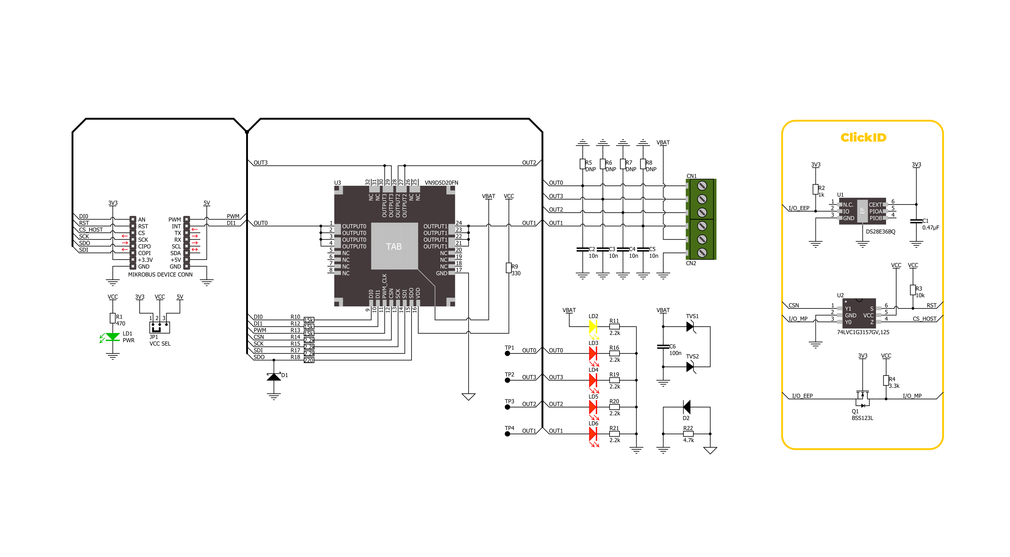
Click board™ Schematic
Step by step
Project assembly

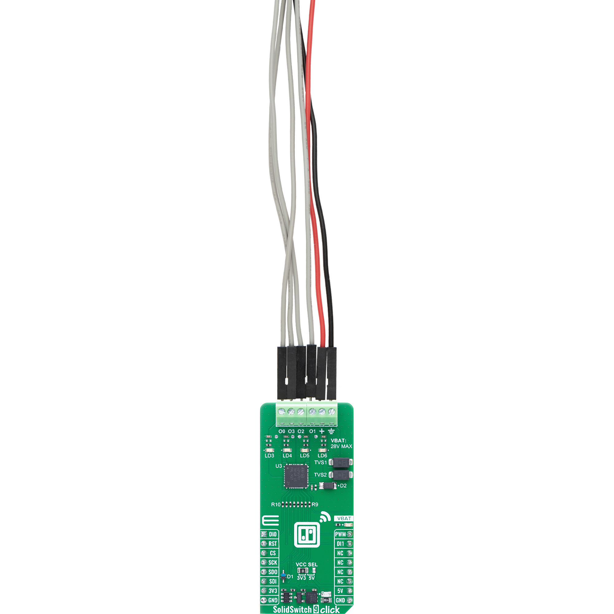
Start by selecting your development board and Click board™. Begin with the Clicker 2 for Kinetis as your development board.


Software Support
Library Description
SolidSwitch 9 Click demo application is developed using the NECTO Studio, ensuring compatibility with mikroSDK's open-source libraries and tools. Designed for plug-and-play implementation and testing, the demo is fully compatible with all development, starter, and mikromedia boards featuring a mikroBUS™ socket.
Example Description
This example demonstrates the use of the SolidSwitch 9 Click board by gradually increasing and decreasing the output duty cycle of each output channel one by one. After each update, the output is enabled and the diagnostic status is cleared.
Key functions:
solidswitch9_cfg_setup- This function initializes Click configuration structure to initial values.solidswitch9_init- This function initializes all necessary pins and peripherals used for this Click board.solidswitch9_default_cfg- This function executes a default configuration of SolidSwitch 9 Click board.solidswitch9_set_out_duty- This function sets the output duty cycle for the selected output channels.solidswitch9_enable_out- This function enables the selected outputs.solidswitch9_clear_all_status- This function clears all status registers on the SolidSwitch 9 Click board.
Application Init
Initializes the logger and the Click board driver, and applies the default configuration.
Application Task
Adjusts the output duty cycle from 0% to 100% and back to 0% for each channel sequentially and clears the diagnostic status after each duty cycle update. The currently active output channel number is logged on the USB UART.
Open Source
Code example
The complete application code and a ready-to-use project are available through the NECTO Studio Package Manager for direct installation in the NECTO Studio. The application code can also be found on the MIKROE GitHub account.
/*!
 * @file main.c
 * @brief SolidSwitch 9 Click example
 *
 * # Description
 * This example demonstrates the use of the SolidSwitch 9 Click board by
 * gradually increasing and decreasing the output duty cycle of each output channel one by one.
 * After each update, the output is enabled and the diagnostic status is cleared.
 *
 * The demo application is composed of two sections:
 *
 * ## Application Init
 * Initializes the logger and the Click board driver, and applies the default configuration.
 *
 * ## Application Task
 * Adjusts the output duty cycle from 0% to 100% and back to 0% for each channel sequentially
 * and clears the diagnostic status after each duty cycle update. The currently active output
 * channel number is logged on the USB UART.
 *
 * @author Stefan Filipovic
 *
 */

#include "board.h"
#include "log.h"
#include "solidswitch9.h"

static solidswitch9_t solidswitch9;
static log_t logger;

void application_init ( void )
{
    log_cfg_t log_cfg;  /**< Logger config object. */
    solidswitch9_cfg_t solidswitch9_cfg;  /**< Click config object. */

    /**
     * Logger initialization.
     * Default baud rate: 115200
     * Default log level: LOG_LEVEL_DEBUG
     * @note If USB_UART_RX and USB_UART_TX
     * are defined as HAL_PIN_NC, you will
     * need to define them manually for log to work.
     * See @b LOG_MAP_USB_UART macro definition for detailed explanation.
     */
    LOG_MAP_USB_UART( log_cfg );
    log_init( &logger, &log_cfg );
    log_info( &logger, " Application Init " );

    // Click initialization.
    solidswitch9_cfg_setup( &solidswitch9_cfg );
    SOLIDSWITCH9_MAP_MIKROBUS( solidswitch9_cfg, MIKROBUS_1 );
    if ( SPI_MASTER_ERROR == solidswitch9_init( &solidswitch9, &solidswitch9_cfg ) )
    {
        log_error( &logger, " Communication init." );
        for ( ; ; );
    }

    if ( SOLIDSWITCH9_ERROR == solidswitch9_default_cfg ( &solidswitch9 ) )
    {
        log_error( &logger, " Default configuration." );
        for ( ; ; );
    }

    log_info( &logger, " Application Task " );
}

void application_task ( void )
{
    static uint8_t out_ch_old = SOLIDSWITCH9_OUT_MASK;
    static uint8_t out_ch = SOLIDSWITCH9_OUT1;
    static int16_t duty = SOLIDSWITCH9_OUT_DUTY_0_PCT;
    static int8_t duty_inc = 1;
    if ( out_ch_old != out_ch )
    {
        log_printf ( &logger, "\r\n Active channel: " );
        if ( SOLIDSWITCH9_OUT3 == out_ch )
        {
            log_printf ( &logger, "3\r\n" );
        }
        else
        {
            log_printf ( &logger, "%u\r\n", ( uint16_t ) ( out_ch >> 1 ) );
        }
        out_ch_old = out_ch;
    }
    solidswitch9_set_out_duty ( &solidswitch9, out_ch, duty );
    solidswitch9_enable_out ( &solidswitch9, out_ch );
    solidswitch9_clear_all_status ( &solidswitch9 );
    duty += duty_inc;
    if ( ( duty > SOLIDSWITCH9_OUT_DUTY_100_PCT ) || ( duty < SOLIDSWITCH9_OUT_DUTY_0_PCT ) )
    {
        if ( duty < SOLIDSWITCH9_OUT_DUTY_0_PCT )
        {
            out_ch <<= 1;
            if ( out_ch > SOLIDSWITCH9_OUT3 )
            {
                out_ch = SOLIDSWITCH9_OUT0;
            }
        }
        duty_inc *= -1;
        duty += duty_inc;
    }
}

int main ( void )
{
    /* Do not remove this line or clock might not be set correctly. */
    #ifdef PREINIT_SUPPORTED
    preinit();
    #endif

    application_init( );

    for ( ; ; )
    {
        application_task( );
    }

    return 0;
}

// ------------------------------------------------------------------------ END
Additional Support
Resources
Category:Power Switch


