Keep your electronics running smoothly with the help of LS12052BD33 and PIC32MZ2048EFM100
Current storm? eFuse to the rescue!

Published Nov 11, 2023
Click board™
eFuse 7 Click
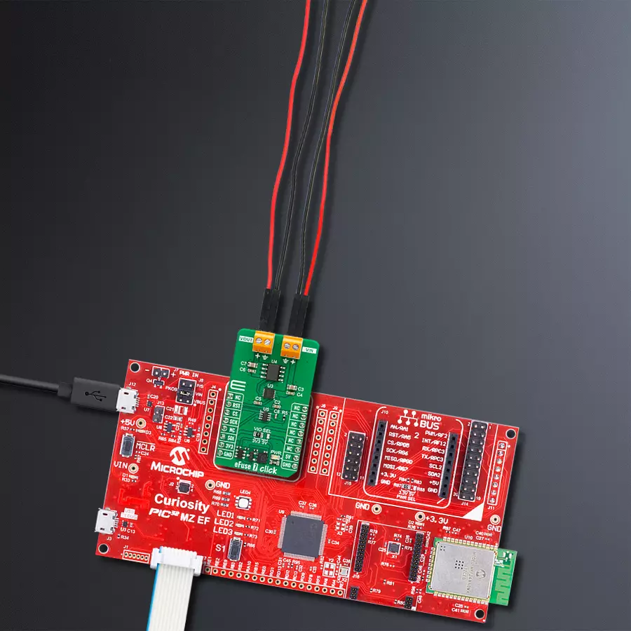
Dev. board
Curiosity PIC32 MZ EF
Compiler
NECTO Studio
MCU
PIC32MZ2048EFM100
Safeguard your electronic circuits from overcurrent events and ensure uninterrupted operation and longevity for your devices.
A
A
Hardware Overview
How does it work?
eFuse 7 Click is based on the LS12052BD33, an eFuse with over-voltage protection and blocking FET control from Littelfuse. It is a current limit load switch with an integrated power load switch designed to manage current/voltage/start-up voltage ramp to the connected load. The internal MOSFET of the device will start conducting and allowing current to flow from IN to OUT as VIN rises by enabling the eFuse with an accurate ON/OFF threshold of 1.29V and 1.19V, respectively. After a Start-Up sequence, the eFuse will actively monitor its load current and input voltage. The eFuse will ensure that any harmful spikes are
safely clamped to a pre-determined level at the output. The eFuse will shut down its internal MOSFET if the overload of the current limit is exceeded or the device’s temperature exceeds its threshold. The eFuse uses the TP86R203NL, an N-channel MOS from Toshiba, as a gate to the output screw terminal. The current limit on this eFuse 7 Click can be programmed. For this purpose, there is the AD5227, a 64-position up/down control digital potentiometer from Analog Devices. This 10K end-to-end potentiometer, in variable resistor configuration, is used to feed the current limit program pin of the eFuse. eFuse 7 Click uses a
simple 3-Wire serial interface of the digital potentiometer to allow the host MCU to set the current limit to this Click board™. Over the RST pin, you can enable the eFuse with the logic HIGH. This Click board™ can operate with either 3.3V or 5V logic voltage levels selected via the VIO SEL jumper. This way, both 3.3V and 5V capable MCUs can use the communication lines properly. Also, this Click board™ comes equipped with a library containing easy-to-use functions and an example code that can be used as a reference for further development.

Features overview
Development board
Curiosity PIC32 MZ EF development board is a fully integrated 32-bit development platform featuring the high-performance PIC32MZ EF Series (PIC32MZ2048EFM) that has a 2MB Flash, 512KB RAM, integrated FPU, Crypto accelerator, and excellent connectivity options. It includes an integrated programmer and debugger, requiring no additional hardware. Users can expand
functionality through MIKROE mikroBUS™ Click™ adapter boards, add Ethernet connectivity with the Microchip PHY daughter board, add WiFi connectivity capability using the Microchip expansions boards, and add audio input and output capability with Microchip audio daughter boards. These boards are fully integrated into PIC32’s powerful software framework, MPLAB Harmony,
which provides a flexible and modular interface to application development a rich set of inter-operable software stacks (TCP-IP, USB), and easy-to-use features. The Curiosity PIC32 MZ EF development board offers expansion capabilities making it an excellent choice for a rapid prototyping board in Connectivity, IOT, and general-purpose applications.

Microcontroller Overview
MCU Card / MCU

Architecture
PIC32
MCU Memory (KB)
2048
Silicon Vendor
Microchip
Pin count
100
RAM (Bytes)
524288
Used MCU Pins
mikroBUS™ mapper
Take a closer look
Click board™ Schematic

Step by step
Project assembly

Start by selecting your development board and Click board™. Begin with the Curiosity PIC32 MZ EF as your development board.


Software Support
Library Description
This library contains API for eFuse 7 Click driver.
Key functions:
efuse7_enable_output- eFuse 7 output enable function.efuse7_wiper_inc- eFuse 7 wiper position increase function.efuse7_set_limit- eFuse 7 set current limit function.
Open Source
Code example
The complete application code and a ready-to-use project are available through the NECTO Studio Package Manager for direct installation in the NECTO Studio. The application code can also be found on the MIKROE GitHub account.
/*!
 * @file main.c
 * @brief eFuse 7 Click Example.
 *
 * # Description
 * This library contains API for the eFuse 7 Click driver.
 * This driver provides the functions to set the current limiting conditions
 * in order to provide the threshold of the fault conditions.
 *
 * The demo application is composed of two sections :
 *
 * ## Application Init
 * Initialization of Click module and UART log, then performing default
 * configuration and setting a current limit to 1 A.
 *
 * ## Application Task
 * This example demonstrates the use of the eFuse 7 Click board.
 * Reading user's input from UART Terminal and using it as an index
 * for an array of pre-calculated values that define the current limit level.
 * Results are being sent to the UART Terminal, where you can track their changes.
 *
 * @author Stefan Ilic
 *
 */

#include "board.h"
#include "log.h"
#include "efuse7.h"

static efuse7_t efuse7;   /**< eFuse 7 Click driver object. */
static log_t logger;      /**< Logger object. */

const uint8_t limit_value_op[ 8 ] =
{
    EFUSE7_CURRENT_LIMIT_1A,
    EFUSE7_CURRENT_LIMIT_2A,
    EFUSE7_CURRENT_LIMIT_2A5,
    EFUSE7_CURRENT_LIMIT_3A,
    EFUSE7_CURRENT_LIMIT_3A5,
    EFUSE7_CURRENT_LIMIT_4A,
    EFUSE7_CURRENT_LIMIT_4A5,
    EFUSE7_CURRENT_LIMIT_5A,
};

static void display_selection ( void )
{
    log_printf( &logger, "  To select current limit  \r\n" );
    log_printf( &logger, "  Send one of the numbers: \r\n" );
    log_printf( &logger, "- - - - - - - - - - - - - -\r\n" );
    log_printf( &logger, " '0' - Limited to 1   A  \r\n" );
    log_printf( &logger, " '1' - Limited to 2   A  \r\n" );
    log_printf( &logger, " '2' - Limited to 2.5 A  \r\n" );
    log_printf( &logger, " '3' - Limited to 3   A  \r\n" );
    log_printf( &logger, " '4' - Limited to 3.5 A  \r\n" );
    log_printf( &logger, " '5' - Limited to 4   A  \r\n" );
    log_printf( &logger, " '6' - Limited to 4.5 A  \r\n" );
    log_printf( &logger, " '7' - Limited to 5   A  \r\n" );
    log_printf( &logger, "---------------------------\r\n" );
}

void application_init ( void )
{
    log_cfg_t log_cfg;  /**< Logger config object. */
    efuse7_cfg_t efuse7_cfg;  /**< Click config object. */

    /**
     * Logger initialization.
     * Default baud rate: 115200
     * Default log level: LOG_LEVEL_DEBUG
     * @note If USB_UART_RX and USB_UART_TX
     * are defined as HAL_PIN_NC, you will
     * need to define them manually for log to work.
     * See @b LOG_MAP_USB_UART macro definition for detailed explanation.
     */
    LOG_MAP_USB_UART( log_cfg );
    log_init( &logger, &log_cfg );
    log_info( &logger, " Application Init " );

    // Click initialization.
    efuse7_cfg_setup( &efuse7_cfg );
    EFUSE7_MAP_MIKROBUS( efuse7_cfg, MIKROBUS_1 );
    if ( DIGITAL_OUT_UNSUPPORTED_PIN == efuse7_init( &efuse7, &efuse7_cfg ) )
    {
        log_error( &logger, " Communication init." );
        for ( ; ; );
    }

    if ( EFUSE7_ERROR == efuse7_default_cfg ( &efuse7 ) )
    {
        log_error( &logger, " Default configuration." );
        for ( ; ; );
    }

    log_info( &logger, " Application Task " );
    display_selection( );
    Delay_ms ( 100 );
}

void application_task ( void )
{
    static char index;

    if ( 1 == log_read( &logger, &index, 1 ) )
    {
        if ( ( index >= '0' ) && ( index <= '7' ) )
        {
            efuse7_set_limit ( &efuse7, limit_value_op[ index - 48 ] );
            log_printf( &logger, "  >>> Selected mode %c     \r\n", index );
            log_printf( &logger, "---------------------------\r\n" );
            Delay_ms ( 100 );
        }
        else
        {
            log_printf( &logger, "    Data not in range!    \r\n" );
            log_printf( &logger, "---------------------------\r\n" );
            display_selection( );
            Delay_ms ( 100 );
        }
    }
}

int main ( void )
{
    /* Do not remove this line or clock might not be set correctly. */
    #ifdef PREINIT_SUPPORTED
    preinit();
    #endif

    application_init( );

    for ( ; ; )
    {
        application_task( );
    }

    return 0;
}

// ------------------------------------------------------------------------ END


