Creates dynamic red visual outputs with MAX7129 and ATmega644
Serial 8x8 red LED matrix display

Published Mar 09, 2025
Click board™
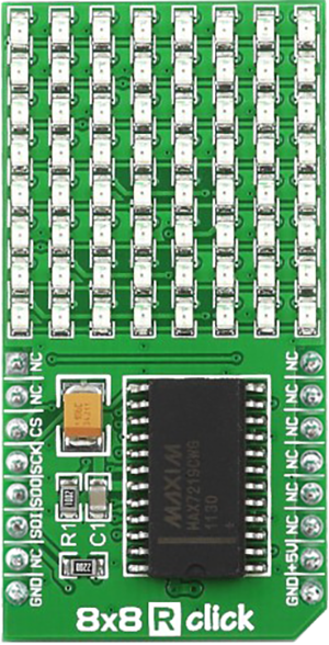
8x8 R Click
Dev. board
EasyAVR v7
Compiler
NECTO Studio
MCU
ATmega644
Create dynamic red LED matrix display perfect for indicators, animations, and real-time visual feedback
A
A
Hardware Overview
How does it work?
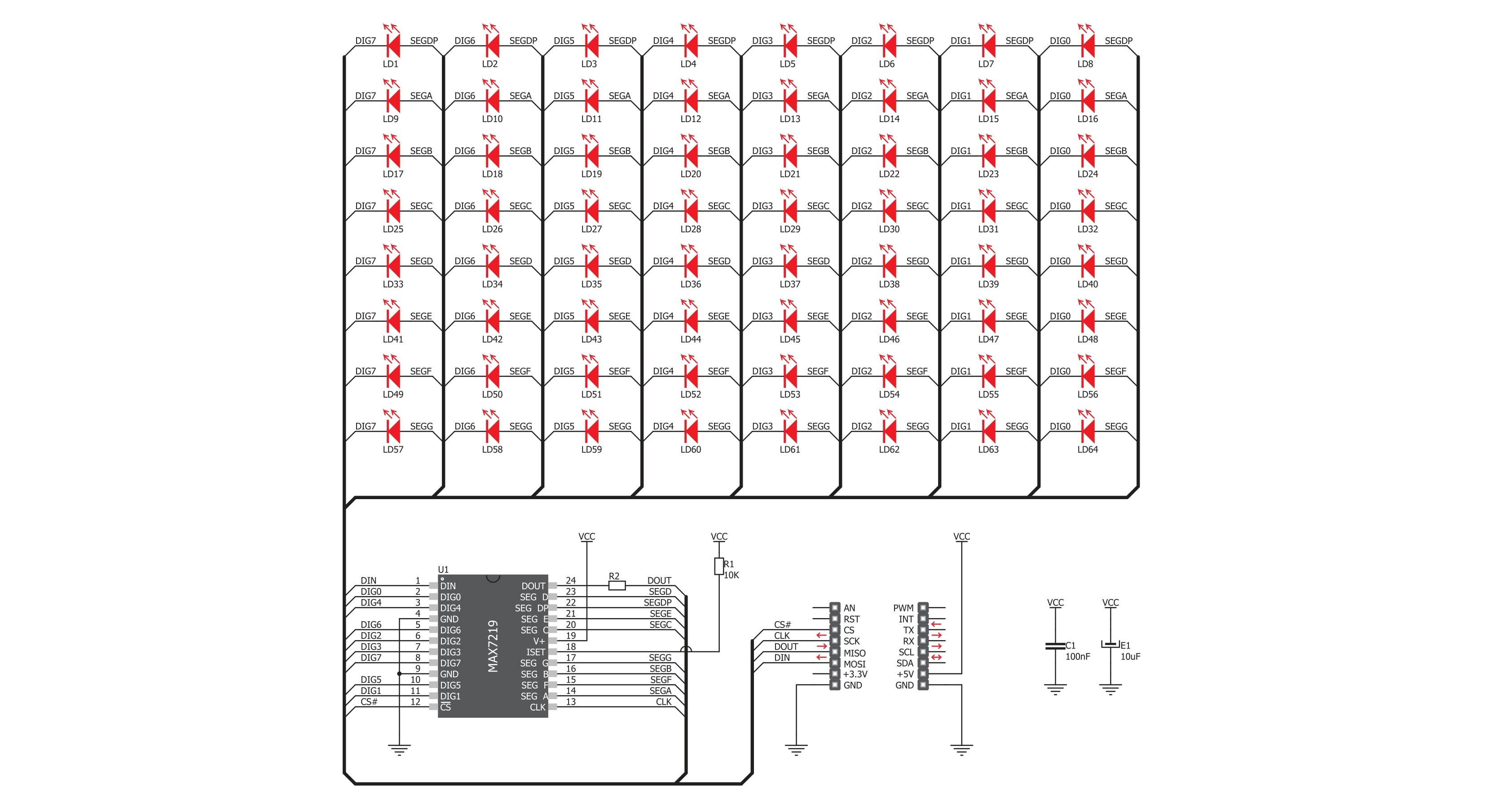
8x8 R Click is a compact 64 red LED matrix display Click board™, featuring a MAX7129 LED driver for precise control. It enables independent LED control, 16-step digital brightness adjustment, and glitch-free startup by blanking the display on power-up. With a fast SPI interface, 8x8 R Click ensures smooth data transmission and quick
response. The MAX7129 IC integrates 8x8 RAM storage, a 16-bit data shifter, a constant current source, and a PWM intensity control register, allowing efficient LED matrix operation. Designed for easy integration, the board requires only one external resistor for current control, simplifying the design. The 800Hz refresh rate ensures flicker-free
performance, while daisy-chaining support allows expansion with multiple modules. Ideal for LED matrix displays, bar graphs, and panel meters, 8x8 R Click provides a reliable solution for visual output in embedded applications.

Features overview
Development board
EasyAVR v7 is the seventh generation of AVR development boards specially designed for the needs of rapid development of embedded applications. It supports a wide range of 16-bit AVR microcontrollers from Microchip and has a broad set of unique functions, such as a powerful onboard mikroProg programmer and In-Circuit debugger over USB. The development board is well organized and designed so that the end-user has all the necessary elements in one place, such as switches, buttons, indicators, connectors, and others. With four different connectors for each port, EasyAVR v7 allows you to connect accessory boards, sensors, and custom electronics more
efficiently than ever. Each part of the EasyAVR v7 development board contains the components necessary for the most efficient operation of the same board. An integrated mikroProg, a fast USB 2.0 programmer with mikroICD hardware In-Circuit Debugger, offers many valuable programming/debugging options and seamless integration with the Mikroe software environment. Besides it also includes a clean and regulated power supply block for the development board. It can use a wide range of external power sources, including an external 12V power supply, 7-12V AC or 9-15V DC via DC connector/screw terminals, and a power source via the USB Type-B (USB-B)
connector. Communication options such as USB-UART and RS-232 are also included, alongside the well-established mikroBUS™ standard, three display options (7-segment, graphical, and character-based LCD), and several different DIP sockets which cover a wide range of 16-bit AVR MCUs. EasyAVR v7 is an integral part of the Mikroe ecosystem for rapid development. Natively supported by Mikroe software tools, it covers many aspects of prototyping and development thanks to a considerable number of different Click boards™ (over a thousand boards), the number of which is growing every day.

Microcontroller Overview
MCU Card / MCU

Architecture
AVR
MCU Memory (KB)
64
Silicon Vendor
Microchip
Pin count
40
RAM (Bytes)
4096
Used MCU Pins
mikroBUS™ mapper
Take a closer look
Click board™ Schematic
Step by step
Project assembly

Start by selecting your development board and Click board™. Begin with the EasyAVR v7 as your development board.


Software Support
Library Description
8x8 R Click demo application is developed using the NECTO Studio, ensuring compatibility with mikroSDK's open-source libraries and tools. Designed for plug-and-play implementation and testing, the demo is fully compatible with all development, starter, and mikromedia boards featuring a mikroBUS™ socket.
Example Description
This demo example shows a drawing of Image, new create string and character on the screen.
Key functions:
c8x8r_cfg_setup- Config Object Initialization function.c8x8r_init- Initialization function.c8x8r_default_cfg- Click Default Configuration function.c8x8r_write_cmd- This function writes a desired number of data bytes starting from the selected register by using SPI serial interface.c8x8r_display_refresh- The function switches off all LEDs.c8x8r_display_byte- This function displayes one character to the display.
Application Init
Configuring Clicks and log objects. Settings the Click in the default configuration.
Application Task
Shows one byte, then scrolls the string and image, every 1 sec.
Open Source
Code example
The complete application code and a ready-to-use project are available through the NECTO Studio Package Manager for direct installation in the NECTO Studio. The application code can also be found on the MIKROE GitHub account.
/*!
 * @file main.c
 * @brief 8x8 R Click example
 *
 * # Description
 * This demo example shows a drawing of Image, new create string and character on the screen.
 *
 * The demo application is composed of two sections :
 *
 * ## Application Init
 * Configuring Clicks and log objects.
 * Settings the Click in the default configuration.
 *
 * ## Application Task
 * Shows one byte, then scrolls the string and image, every 1 sec.
 *
 * @author Stefan Ilic
 *
 */

#include "board.h"
#include "log.h"
#include "c8x8r.h"

static c8x8r_t c8x8r;
static log_t logger;

uint8_t demo_string[ 11 ] = { ' ', '-', 'M', 'i', 'k', 'r', 'o', 'E', '-', ' ', 0 };
uint8_t demo_img_on[ 8 ] = { 0x08, 0x1c, 0x36, 0x22, 0x08, 0x1c, 0x36, 0x22 };
uint8_t demo_img_off[ 8 ] = { 0xf7, 0xe3, 0xc9, 0xdd, 0xf7, 0xe3, 0xc9, 0xdd };
char demo_char = 'A';

void application_init ( void ) {
    log_cfg_t log_cfg;  /**< Logger config object. */
    c8x8r_cfg_t c8x8r_cfg;  /**< Click config object. */

    /**
     * Logger initialization.
     * Default baud rate: 115200
     * Default log level: LOG_LEVEL_DEBUG
     * @note If USB_UART_RX and USB_UART_TX
     * are defined as HAL_PIN_NC, you will
     * need to define them manually for log to work.
     * See @b LOG_MAP_USB_UART macro definition for detailed explanation.
     */
    LOG_MAP_USB_UART( log_cfg );
    log_init( &logger, &log_cfg );
    log_info( &logger, " Application Init " );

    // Click initialization.

    c8x8r_cfg_setup( &c8x8r_cfg );
    C8X8R_MAP_MIKROBUS( c8x8r_cfg, MIKROBUS_1 );
    err_t init_flag  = c8x8r_init( &c8x8r, &c8x8r_cfg );
    if ( init_flag == SPI_MASTER_ERROR ) {
        log_info( &logger, " Application Init Error. " );
        log_info( &logger, " Please, run program again... " );

        for ( ; ; );
    }

    c8x8r_default_cfg ( &c8x8r );
    log_info( &logger, " Application Task " );
    Delay_ms ( 1000 );
}

void application_task ( void ) {
    c8x8r_display_byte( &c8x8r, demo_char );
    Delay_ms ( 1000 );

    c8x8r_display_string( &c8x8r, &demo_string[ 0 ] );
    Delay_ms ( 1000 );

    c8x8r_display_image( &c8x8r, &demo_img_on[ 0 ] );
    Delay_ms ( 1000 );

    c8x8r_display_image( &c8x8r, &demo_img_off[ 0 ] );
    Delay_ms ( 1000 );
}

int main ( void )
{
    /* Do not remove this line or clock might not be set correctly. */
    #ifdef PREINIT_SUPPORTED
    preinit();
    #endif

    application_init( );

    for ( ; ; )
    {
        application_task( );
    }

    return 0;
}

// ------------------------------------------------------------------------ END
Additional Support
Resources
Category:LED Matrix


