Measure distances within the 20- to 500cm range with TMF8806-1A and ATmega328
Precise time-of-flight distance measurement solution

Published Feb 04, 2025
Click board™
LightRanger 13 Click
Dev. board
Arduino UNO Rev3
Compiler
NECTO Studio
MCU
ATmega328
Measure distances precisely and reliably with advanced TOF technology perfect for robotics, automation, and smart appliances
A
A
Hardware Overview
How does it work?
LightRanger 13 Click is based on the TMF8806-1A, a time-of-flight (TOF) sensor from ams OSRAM designed for precise distance measurement in various applications. This sensor is housed in one of the smallest modular packages in the industry and incorporates a 940nm VCSEL that complies with Class 1 eye safety standards. Using single-photon avalanche diode (SPAD) technology, a fast time-to-digital converter (TDC) architecture, and on-chip histogram processing, the TMF8806-1A ensures highly accurate distance measurements across a detection range of 1cm to 500cm, even in challenging environments. This Click board™ is ideal for industrial, commercial, and residential use cases requiring high-resolution distance sensing, such as robotics, home and building automation, projection and display systems, factory automation, access control, security systems, and smart appliances. The sensor's dTOF technology, combined with its high-sensitivity SPAD detection, delivers exceptional signal-to-noise ratios and a wide dynamic range, ensuring reliable performance in both low-light and bright sunlight conditions. Its fast sub-nanosecond light pulse capability and 30Hz sensing rate enable rapid and precise
distance detection, making it suitable for dynamic applications. The TMF8806-1A features built-in mechanisms for calibration, dirt and smudge removal, and crosstalk compensation, ensuring consistent accuracy over time. Additionally, its integrated eye-safety circuitry halts the VCSEL driver in case of a fault, enhancing operational safety. This Click board™ is designed in a unique format supporting the newly introduced MIKROE feature called "Click Snap." Unlike the standardized version of Click boards, this feature allows the main IC area to become movable by breaking the PCB, opening up many new possibilities for implementation. Thanks to the Snap feature, the TMF8806-1A can operate autonomously by accessing its signals directly on the pins marked 1-8. Additionally, the Snap part includes a specified and fixed screw hole position, enabling users to secure the Snap board in their desired location. LightRanger 13 Click communicates with the host MCU through an I2C interface, supporting a maximum clock frequency of 1MHz for fast data exchange. In addition to the standard interface pins, the board also features an EN pin, which acts as the device enable pin. Setting this pin to a HIGH
logic level powers up the device, while setting it to LOW forces the sensor into a Shutdown mode, during which all memory content is erased. The board also includes an INT pin, configured as an open-drain interrupt output, which signals the host MCU when a ranging measurement is available, ensuring timely data processing. Additionally, the Snap section of the board includes a GPIO0 SEL jumper, which allows for the selection of the TMF8806-1A's I/O supply voltage. Setting the jumper to the VCC position enables a 3.3V or lower supply, such as 1.8V, while setting it to the GND position provides an even lower I/O supply voltage of 1.2V. After startup, the GPIO0 pin can function as a general-purpose GPIO output signal, accessible through the GPIO1 test point on the back of the board. This Click board™ can be operated only with a 3.3V logic voltage level. The board must perform appropriate logic voltage level conversion before using MCUs with different logic levels. It also comes equipped with a library containing functions and example code that can be used as a reference for further development.

Features overview
Development board
Arduino UNO is a versatile microcontroller board built around the ATmega328P chip. It offers extensive connectivity options for various projects, featuring 14 digital input/output pins, six of which are PWM-capable, along with six analog inputs. Its core components include a 16MHz ceramic resonator, a USB connection, a power jack, an
ICSP header, and a reset button, providing everything necessary to power and program the board. The Uno is ready to go, whether connected to a computer via USB or powered by an AC-to-DC adapter or battery. As the first USB Arduino board, it serves as the benchmark for the Arduino platform, with "Uno" symbolizing its status as the
first in a series. This name choice, meaning "one" in Italian, commemorates the launch of Arduino Software (IDE) 1.0. Initially introduced alongside version 1.0 of the Arduino Software (IDE), the Uno has since become the foundational model for subsequent Arduino releases, embodying the platform's evolution.

Microcontroller Overview
MCU Card / MCU

Architecture
AVR
MCU Memory (KB)
32
Silicon Vendor
Microchip
Pin count
32
RAM (Bytes)
2048
You complete me!
Accessories
Click Shield for Arduino UNO has two proprietary mikroBUS™ sockets, allowing all the Click board™ devices to be interfaced with the Arduino UNO board without effort. The Arduino Uno, a microcontroller board based on the ATmega328P, provides an affordable and flexible way for users to try out new concepts and build prototypes with the ATmega328P microcontroller from various combinations of performance, power consumption, and features. The Arduino Uno has 14 digital input/output pins (of which six can be used as PWM outputs), six analog inputs, a 16 MHz ceramic resonator (CSTCE16M0V53-R0), a USB connection, a power jack, an ICSP header, and reset button. Most of the ATmega328P microcontroller pins are brought to the IO pins on the left and right edge of the board, which are then connected to two existing mikroBUS™ sockets. This Click Shield also has several switches that perform functions such as selecting the logic levels of analog signals on mikroBUS™ sockets and selecting logic voltage levels of the mikroBUS™ sockets themselves. Besides, the user is offered the possibility of using any Click board™ with the help of existing bidirectional level-shifting voltage translators, regardless of whether the Click board™ operates at a 3.3V or 5V logic voltage level. Once you connect the Arduino UNO board with our Click Shield for Arduino UNO, you can access hundreds of Click boards™, working with 3.3V or 5V logic voltage levels.

Used MCU Pins
mikroBUS™ mapper
Take a closer look
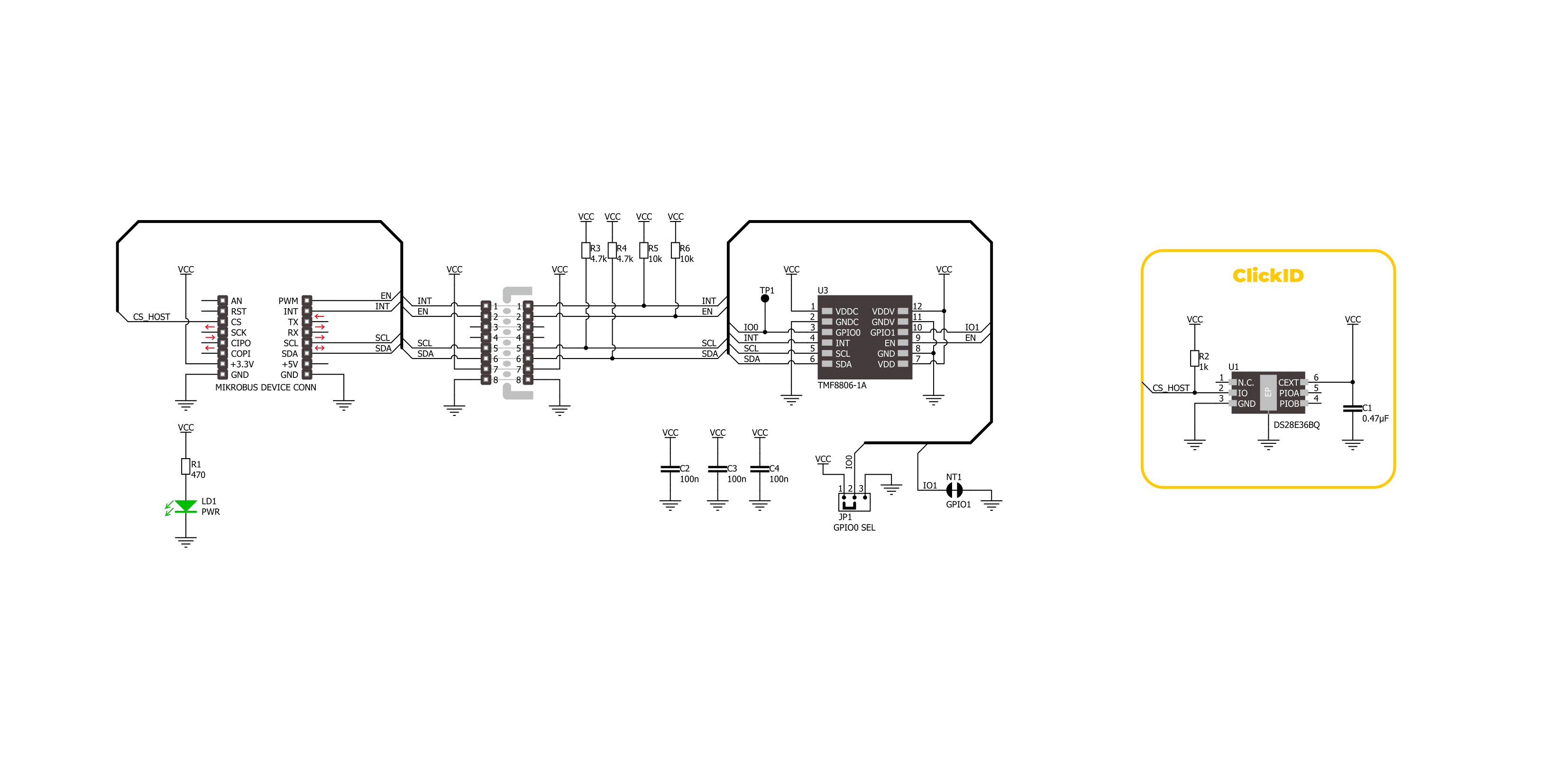
Click board™ Schematic
Step by step
Project assembly

Start by selecting your development board and Click board™. Begin with the Arduino UNO Rev3 as your development board.


Track your results in real time
Application Output
1. Application Output - In Debug mode, the 'Application Output' window enables real-time data monitoring, offering direct insight into execution results. Ensure proper data display by configuring the environment correctly using the provided tutorial.

2. UART Terminal - Use the UART Terminal to monitor data transmission via a USB to UART converter, allowing direct communication between the Click board™ and your development system. Configure the baud rate and other serial settings according to your project's requirements to ensure proper functionality. For step-by-step setup instructions, refer to the provided tutorial.

3. Plot Output - The Plot feature offers a powerful way to visualize real-time sensor data, enabling trend analysis, debugging, and comparison of multiple data points. To set it up correctly, follow the provided tutorial, which includes a step-by-step example of using the Plot feature to display Click board™ readings. To use the Plot feature in your code, use the function: plot(*insert_graph_name*, variable_name);. This is a general format, and it is up to the user to replace 'insert_graph_name' with the actual graph name and 'variable_name' with the parameter to be displayed.

Software Support
Library Description
LightRanger 13 Click demo application is developed using the NECTO Studio, ensuring compatibility with mikroSDK's open-source libraries and tools. Designed for plug-and-play implementation and testing, the demo is fully compatible with all development, starter, and mikromedia boards featuring a mikroBUS™ socket.
Example Description
This application demonstrates the usage of the LightRanger 13 Click for distance measurement and monitoring.
Key functions:
lightranger13_cfg_setup- Config Object Initialization function.lightranger13_init- Initialization function.lightranger13_default_cfg- Click Default Configuration function.lightranger13_set_threshold- This function sets a threshold level and interrupt persistance.lightranger13_start_measurement- This function starts a measurement (the configuration, factory calibration and state data are used from context object).lightranger13_read_result- This function reads the measurement results.
Application Init
Initializes the logger and LightRanger 13 Click with default configuration, displays device information, performs factory calibration (if enabled), and sets up distance measurement thresholds (1mm-1000mm) with persistence (5 consecutive times) to ensure reliable readings. It then starts the measurement process.
Application Task
Waits for the data ready interrupt signal, indicating a new measurement is available. Upon receiving the signal, it reads the distance and temperature data from the sensor and logs the values to USB UART.
Open Source
Code example
The complete application code and a ready-to-use project are available through the NECTO Studio Package Manager for direct installation in the NECTO Studio. The application code can also be found on the MIKROE GitHub account.
/*!
 * @file main.c
 * @brief LightRanger 13 Click example
 *
 * # Description
 * This application demonstrates the usage of the LightRanger 13 Click for distance
 * measurement and monitoring.
 *
 * The demo application is composed of two sections:
 *
 * ## Application Init
 * Initializes the logger and LightRanger 13 Click with default configuration,
 * displays device information, performs factory calibration (if enabled), and sets up
 * distance measurement thresholds (1mm-1000mm) with persistence (5 consecutive times)
 * to ensure reliable readings. It then starts the measurement process.
 *
 * ## Application Task
 * Waits for the data ready interrupt signal, indicating a new measurement is available.
 * Upon receiving the signal, it reads the distance and temperature data from the sensor
 * and logs the values to USB UART.
 *
 * @note
 * The factory calibration step can be enabled or disabled by commenting/uncommenting
 * the `FACTORY_CALIBRATION_DISABLE` macro.
 *
 * @author Stefan Filipovic
 *
 */

#include "board.h"
#include "log.h"
#include "lightranger13.h"

// Comment out the line below to enable factory calibration
#define FACTORY_CALIBRATION_DISABLE

static lightranger13_t lightranger13;
static log_t logger;

void application_init ( void )
{
    log_cfg_t log_cfg;  /**< Logger config object. */
    lightranger13_cfg_t lightranger13_cfg;  /**< Click config object. */

    /**
     * Logger initialization.
     * Default baud rate: 115200
     * Default log level: LOG_LEVEL_DEBUG
     * @note If USB_UART_RX and USB_UART_TX
     * are defined as HAL_PIN_NC, you will
     * need to define them manually for log to work.
     * See @b LOG_MAP_USB_UART macro definition for detailed explanation.
     */
    LOG_MAP_USB_UART( log_cfg );
    log_init( &logger, &log_cfg );
    log_info( &logger, " Application Init " );

    // Click initialization.
    lightranger13_cfg_setup( &lightranger13_cfg );
    LIGHTRANGER13_MAP_MIKROBUS( lightranger13_cfg, MIKROBUS_1 );
    if ( I2C_MASTER_ERROR == lightranger13_init( &lightranger13, &lightranger13_cfg ) )
    {
        log_error( &logger, " Communication init." );
        for ( ; ; );
    }

    if ( LIGHTRANGER13_ERROR == lightranger13_default_cfg ( &lightranger13 ) )
    {
        log_error( &logger, " Default configuration." );
        for ( ; ; );
    }

    log_printf( &logger, "--- DEVICE INFO ---\r\n" );
    log_printf( &logger, " App version: %u.%u.%u.%u\r\n",
                ( uint16_t ) lightranger13.info.app_ver[ 0 ],
                ( uint16_t ) lightranger13.info.app_ver[ 1 ],
                ( uint16_t ) lightranger13.info.app_ver[ 2 ],
                ( uint16_t ) lightranger13.info.app_ver[ 3 ] );
    log_printf( &logger, " Chip version: %u.%u\r\n",
                ( uint16_t ) lightranger13.info.chip_ver[ 0 ],
                ( uint16_t ) lightranger13.info.chip_ver[ 1 ] );
    log_printf( &logger, " Serial number: %.8LX\r\n\n", lightranger13.info.serial_num );
    Delay_ms ( 1000 );

#ifndef FACTORY_CALIBRATION_DISABLE
    log_printf( &logger, "--- FACTORY CALIBRATION ---\r\n" );
    log_printf( &logger, " Calibration environment:\r\n" );
    log_printf( &logger, " - Device has to be in the final (correct) optical stack\r\n" );
    Delay_ms ( 10 );
    log_printf( &logger, " - Cover glass (no smudge on the glass) in front of the device\r\n" );
    log_printf( &logger, " - No target in front of the device within 40cm\r\n" );
    log_printf( &logger, " - Dark room or low ambient light\r\n" );
    log_printf( &logger, " Performing factory calibration in 5 seconds...\r\n" );
    for ( uint8_t cnt = 5; cnt > 0; cnt-- )
    {
        log_printf( &logger, " %u\r\n", ( uint16_t ) cnt );
        Delay_ms ( 1000 );
    }
    if ( LIGHTRANGER13_ERROR == lightranger13_factory_calib ( &lightranger13 ) )
    {
        log_error( &logger, " Factory calibration." );
        for ( ; ; );
    }
    log_printf( &logger, " Factory calibration DONE.\r\n\n" );
    Delay_ms ( 1000 );
#endif

    log_printf( &logger, "--- THRESHOLD AND PERSISTANCE ---\r\n" );
    log_printf( &logger, " Setting threshold: 1mm-1000mm; and persistance: 5 times\r\n" );
    if ( LIGHTRANGER13_ERROR == lightranger13_set_threshold ( &lightranger13, 1, 1000, 5 ) )
    {
        log_error( &logger, " Set threshold." );
        for ( ; ; );
    }
    log_printf( &logger, " Set threshold DONE.\r\n\n" );
    Delay_ms ( 1000 );

    log_printf( &logger, "--- STARTING MEASUREMENT ---\r\n" );
    if ( LIGHTRANGER13_ERROR == lightranger13_start_measurement ( &lightranger13 ) )
    {
        log_error( &logger, " Start measurement." );
        for ( ; ; );
    }
    log_printf( &logger, " Measurement started.\r\n\n" );
    Delay_ms ( 1000 );

    log_info( &logger, " Application Task " );
}

void application_task ( void )
{
    lightranger13_meas_result_t result;
    // Wait for data ready interrupt
    while ( lightranger13_get_int_pin ( &lightranger13 ) );

    lightranger13_clear_interrupts ( &lightranger13 );

    if ( LIGHTRANGER13_OK == lightranger13_read_result ( &lightranger13, &result ) )
    {
        log_printf( &logger, " Distance: %u mm\r\n", result.dist_peak );
        log_printf( &logger, " Temperature: %d degC\r\n\n", ( int16_t ) result.temperature );
    }
}

int main ( void )
{
    /* Do not remove this line or clock might not be set correctly. */
    #ifdef PREINIT_SUPPORTED
    preinit();
    #endif

    application_init( );

    for ( ; ; )
    {
        application_task( );
    }

    return 0;
}

// ------------------------------------------------------------------------ END
Additional Support
Resources
Category:Optical


