Add flexible high-current step-down power for embedded systems with the TPS6286B08 and PIC32MZ2048EFH100
High-current, adjustable step-down power solution for FPGAs, CPUs, and ASICs

Published Oct 16, 2025
Click board™
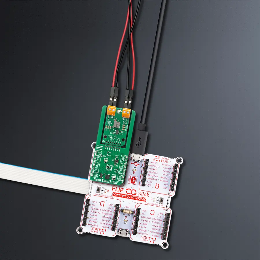
Smart Buck 8 Click
Dev. board
Flip&Click PIC32MZ
Compiler
NECTO Studio
MCU
PIC32MZ2048EFH100
Fine-tune the output voltage from 0.4V to 1.675V in precise 5mV steps, giving you ultimate control over your power rail
A
A
Hardware Overview
How does it work?
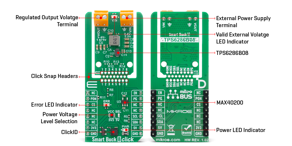
Smart Buck 8 Click is based on the TPS6286B08, a high-frequency, synchronous step-down converter from Texas Instruments designed to deliver excellent transient response over a broad load current range. Operating in pulse width modulation (PWM) mode at medium to heavy loads and automatically entering power save mode at light loads, this device ensures optimal energy efficiency in every operating condition. Its DCS-Control architecture contributes to outstanding load transient performance and tight output voltage regulation, making it highly suitable for applications demanding stable and precise power delivery like supplying core voltages to FPGAs, CPUs, ASICs, and DSPs, as well as for use in machine vision cameras, IP network cameras, and solid-state drives. Smart Buck 8 Click supports an input voltage range from 2.4V to 5.5V at the VIN terminal, where a green VIN LED indicates the presence of external power, and provides an output voltage adjustable from 0.4V to 1.675V with fine 5mV dynamic voltage scaling (DVS) step size via the I2C interface. With a start-up voltage as low as
0.9V and a maximum output current capability of 8A, it can power high-performance digital loads while maintaining thermal stability and robust fault protection. The integrated HICCUP short-circuit protection and thermal shutdown safeguard the system against overloads and excessive temperatures, ensuring reliable operation in demanding environments. This Click board™ is designed in a unique format supporting the newly introduced MIKROE feature called "Click Snap." Unlike the standardized version of Click boards, this feature allows the main sensor/IC/module area to become movable by breaking the PCB, opening up many new possibilities for implementation. Thanks to the Snap feature, the TPS6286B08 can operate autonomously by accessing its signals directly on the pins marked 1-8. Additionally, the Snap part includes a specified and fixed screw hole position, enabling users to secure the Snap board in their desired location. Communication with the host microcontroller is established over an I2C interface supporting clock speeds up to 3.4MHz, with a fixed address of 0x42 and defined read and
write access frames. To optimize power control and operational management, the board also integrates the MAX40200 from Analog Devices, which enables or disables the TPS6286B08 through the dedicated PON pin. A dedicated EN pin allows for external enable/disable control of the entire power module, supporting power domain management in software-controlled power sequencing scenarios. Additionally, there is also a Power Good (PG pin) output that is also routed to an onboard red LED labeled ERROR, which provides real-time visual indication of any voltage irregularities or faults - indicate valid and stable output voltages. This Click board™ can operate with either 3.3V or 5V logic voltage levels selected via the VCC SEL jumper. This way, both 3.3V and 5V capable MCUs can use the communication lines properly. Also, this Click board™ comes equipped with a library containing easy-to-use functions and an example code that can be used as a reference for further development.
Features overview
Development board
Flip&Click PIC32MZ is a compact development board designed as a complete solution that brings the flexibility of add-on Click boards™ to your favorite microcontroller, making it a perfect starter kit for implementing your ideas. It comes with an onboard 32-bit PIC32MZ microcontroller, the PIC32MZ2048EFH100 from Microchip, four mikroBUS™ sockets for Click board™ connectivity, two USB connectors, LED indicators, buttons, debugger/programmer connectors, and two headers compatible with Arduino-UNO pinout. Thanks to innovative manufacturing technology,
it allows you to build gadgets with unique functionalities and features quickly. Each part of the Flip&Click PIC32MZ development kit contains the components necessary for the most efficient operation of the same board. In addition, there is the possibility of choosing the Flip&Click PIC32MZ programming method, using the chipKIT bootloader (Arduino-style development environment) or our USB HID bootloader using mikroC, mikroBasic, and mikroPascal for PIC32. This kit includes a clean and regulated power supply block through the USB Type-C (USB-C) connector. All communication
methods that mikroBUS™ itself supports are on this board, including the well-established mikroBUS™ socket, user-configurable buttons, and LED indicators. Flip&Click PIC32MZ development kit allows you to create a new application in minutes. Natively supported by Mikroe software tools, it covers many aspects of prototyping thanks to a considerable number of different Click boards™ (over a thousand boards), the number of which is growing every day.

Microcontroller Overview
MCU Card / MCU

Architecture
PIC32
MCU Memory (KB)
2048
Silicon Vendor
Microchip
Pin count
100
RAM (Bytes)
524288
Used MCU Pins
mikroBUS™ mapper
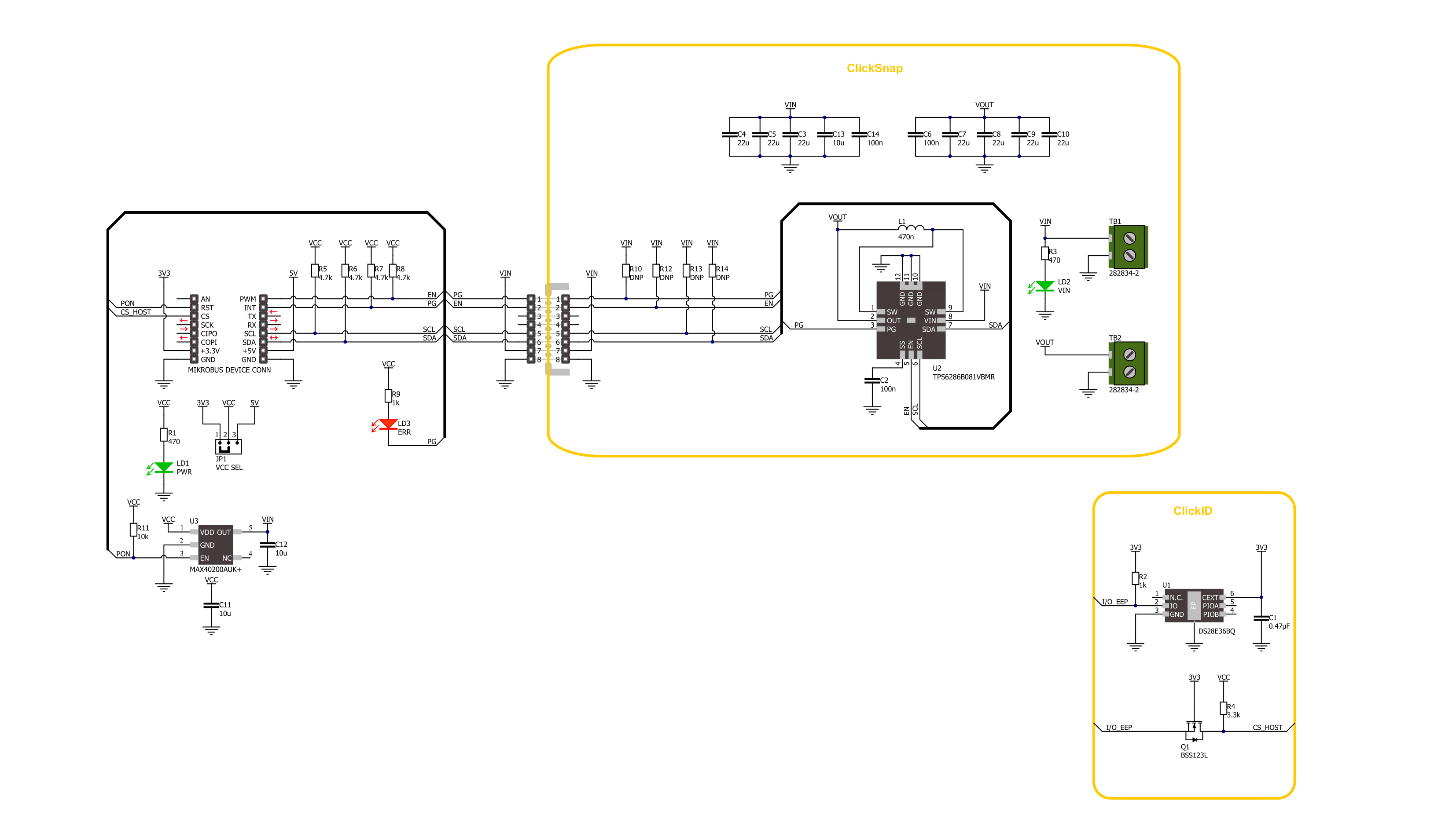
Take a closer look
Click board™ Schematic
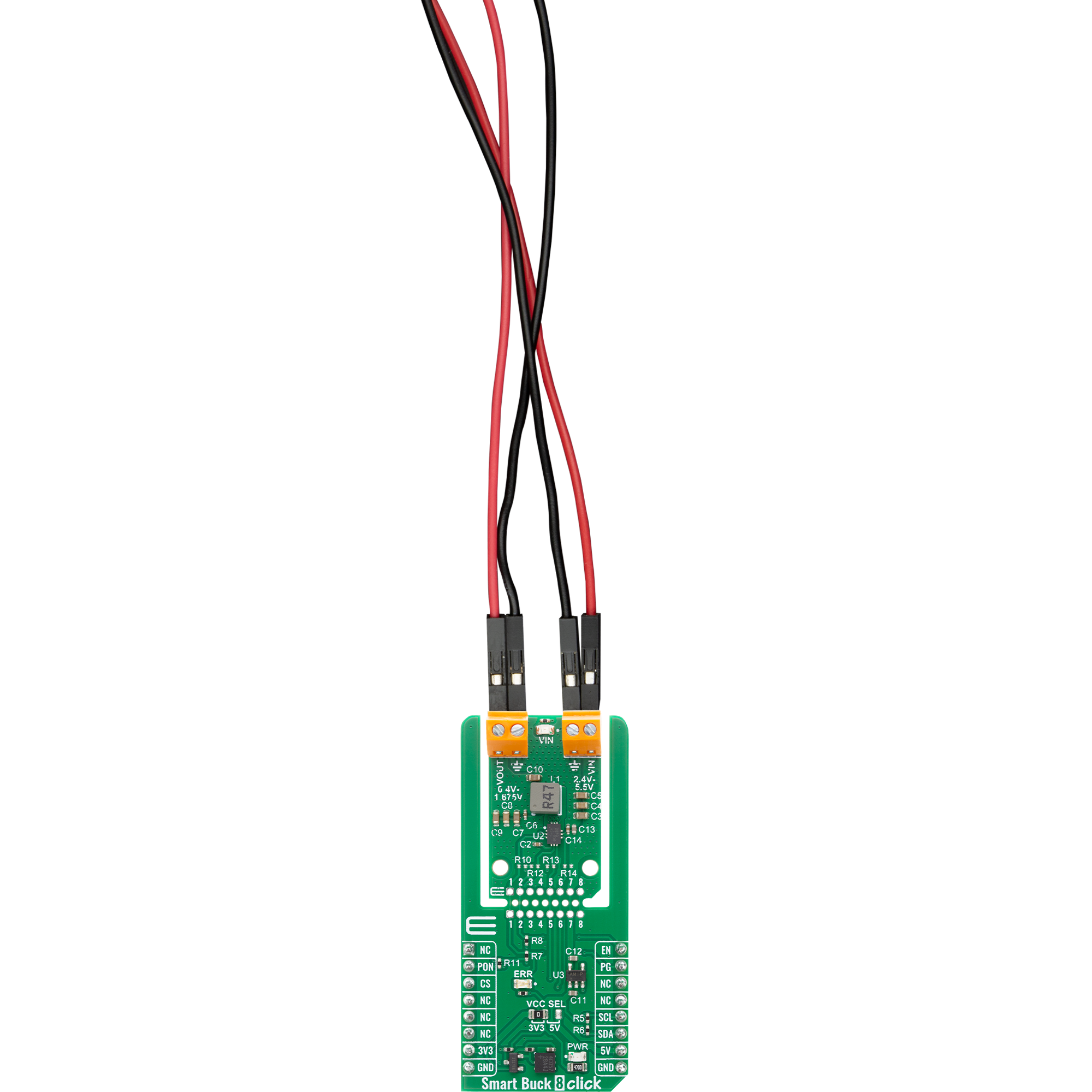
Step by step
Project assembly

Start by selecting your development board and Click board™. Begin with the Flip&Click PIC32MZ as your development board.


Software Support
Library Description
Smart Buck 8 Click demo application is developed using the NECTO Studio, ensuring compatibility with mikroSDK's open-source libraries and tools. Designed for plug-and-play implementation and testing, the demo is fully compatible with all development, starter, and mikromedia boards featuring a mikroBUS™ socket.
Example Description
This example demonstrates the use of the Smart Buck 8 Click board. The application cyclically adjusts the output voltage between its minimum and maximum values in steps and monitors the PG (Power Good) pin for any fault conditions. It logs any detected faults including undervoltage lockout, thermal warning, or hiccup event status.
Key functions:
smartbuck8_cfg_setup- This function initializes Click configuration structure to initial values.smartbuck8_init- This function initializes all necessary pins and peripherals used for this Click board.smartbuck8_default_cfg- This function executes a default configuration of Smart Buck 8 Click board.smartbuck8_get_pg_pin- This function reads the logic level of the PG (power-good) pin.smartbuck8_read_status- This function reads the value of the STATUS register and returns it via output pointer.smartbuck8_set_vout- This function sets the output voltage by writing a scaled value to the VOUT register.
Application Init
Initializes the logger and the Smart Buck 8 Click driver, and applies the default configuration.
Application Task
Cycles the output voltage up and down between the minimum and maximum supported values. Checks for fault conditions via the PG pin and logs detailed status flags if any fault is detected.
Open Source
Code example
The complete application code and a ready-to-use project are available through the NECTO Studio Package Manager for direct installation in the NECTO Studio. The application code can also be found on the MIKROE GitHub account.
/*!
 * @file main.c
 * @brief Smart Buck 8 Click example
 *
 * # Description
 * This example demonstrates the use of the Smart Buck 8 Click board. The application cyclically adjusts
 * the output voltage between its minimum and maximum values in steps and monitors the PG (Power Good) pin
 * for any fault conditions. It logs any detected faults including undervoltage lockout, thermal warning,
 * or hiccup event status.
 *
 * The demo application is composed of two sections :
 *
 * ## Application Init
 * Initializes the logger and the Smart Buck 8 Click driver, and applies the default configuration.
 *
 * ## Application Task
 * Cycles the output voltage up and down between the minimum and maximum supported values.
 * Checks for fault conditions via the PG pin and logs detailed status flags if any fault is detected.
 *
 * @author Stefan Filipovic
 *
 */

#include "board.h"
#include "log.h"
#include "smartbuck8.h"

static smartbuck8_t smartbuck8;
static log_t logger;

void application_init ( void )
{
    log_cfg_t log_cfg;  /**< Logger config object. */
    smartbuck8_cfg_t smartbuck8_cfg;  /**< Click config object. */

    /**
     * Logger initialization.
     * Default baud rate: 115200
     * Default log level: LOG_LEVEL_DEBUG
     * @note If USB_UART_RX and USB_UART_TX
     * are defined as HAL_PIN_NC, you will
     * need to define them manually for log to work.
     * See @b LOG_MAP_USB_UART macro definition for detailed explanation.
     */
    LOG_MAP_USB_UART( log_cfg );
    log_init( &logger, &log_cfg );
    log_info( &logger, " Application Init " );

    // Click initialization.
    smartbuck8_cfg_setup( &smartbuck8_cfg );
    SMARTBUCK8_MAP_MIKROBUS( smartbuck8_cfg, MIKROBUS_1 );
    if ( I2C_MASTER_ERROR == smartbuck8_init( &smartbuck8, &smartbuck8_cfg ) )
    {
        log_error( &logger, " Communication init." );
        for ( ; ; );
    }

    if ( SMARTBUCK8_ERROR == smartbuck8_default_cfg ( &smartbuck8 ) )
    {
        log_error( &logger, " Default configuration." );
        for ( ; ; );
    }

    log_info( &logger, " Application Task " );
}

void application_task ( void )
{
    static uint16_t vout = SMARTBUCK8_VOUT_MV_MIN;
    static int16_t vout_step = 50;
    static uint8_t status = 0;
    if ( !smartbuck8_get_pg_pin ( &smartbuck8 ) )
    {
        log_printf( &logger, "\r\n Fault indication detected via PG pin!\r\n" );
        if ( SMARTBUCK8_OK == smartbuck8_read_status ( &smartbuck8, &status ) )
        {
            if ( status & SMARTBUCK8_STATUS_THERMAL_WARNING )
            {
                log_printf ( &logger, " Junction temperature is higher than 130C\r\n" );
            }
            if ( status & SMARTBUCK8_STATUS_HICCUP )
            {
                log_printf ( &logger, " Device has HICCUP status once\r\n" );
            }
            if ( status & SMARTBUCK8_STATUS_UVLO )
            {
                log_printf ( &logger, " The input voltage is less than UVLO threshold (falling edge)\r\n" );
            }
        }
    }
    if ( SMARTBUCK8_OK == smartbuck8_set_vout ( &smartbuck8, vout ) )
    {
        log_printf ( &logger, "\r\n VOUT: %u mV\r\n", vout );
        vout += vout_step;
        if ( ( vout > SMARTBUCK8_VOUT_MV_MAX ) || ( vout < SMARTBUCK8_VOUT_MV_MIN ) )
        {
            vout_step = -vout_step;
            vout += vout_step;
            vout += vout_step;
        }
    }
    Delay_ms ( 1000 );
    Delay_ms ( 1000 );
}

int main ( void )
{
    /* Do not remove this line or clock might not be set correctly. */
    #ifdef PREINIT_SUPPORTED
    preinit();
    #endif

    application_init( );

    for ( ; ; )
    {
        application_task( );
    }

    return 0;
}

// ------------------------------------------------------------------------ END
Additional Support
Resources
Category:Buck


