Convert a higher input voltage to a lower output voltage with TPS62902 and STM32F031K6
Synchronous DC-DC step-down voltage converter

Published Nov 20, 2024
Click board™
Step Down 12 Click
Dev. board
Nucleo 32 with STM32F031K6 MCU
Compiler
NECTO Studio
MCU
STM32F031K6
Achieve stable DC-DC conversion with precise voltage control perfect for factory automation, data centers, and motor drives
A
A
Hardware Overview
How does it work?
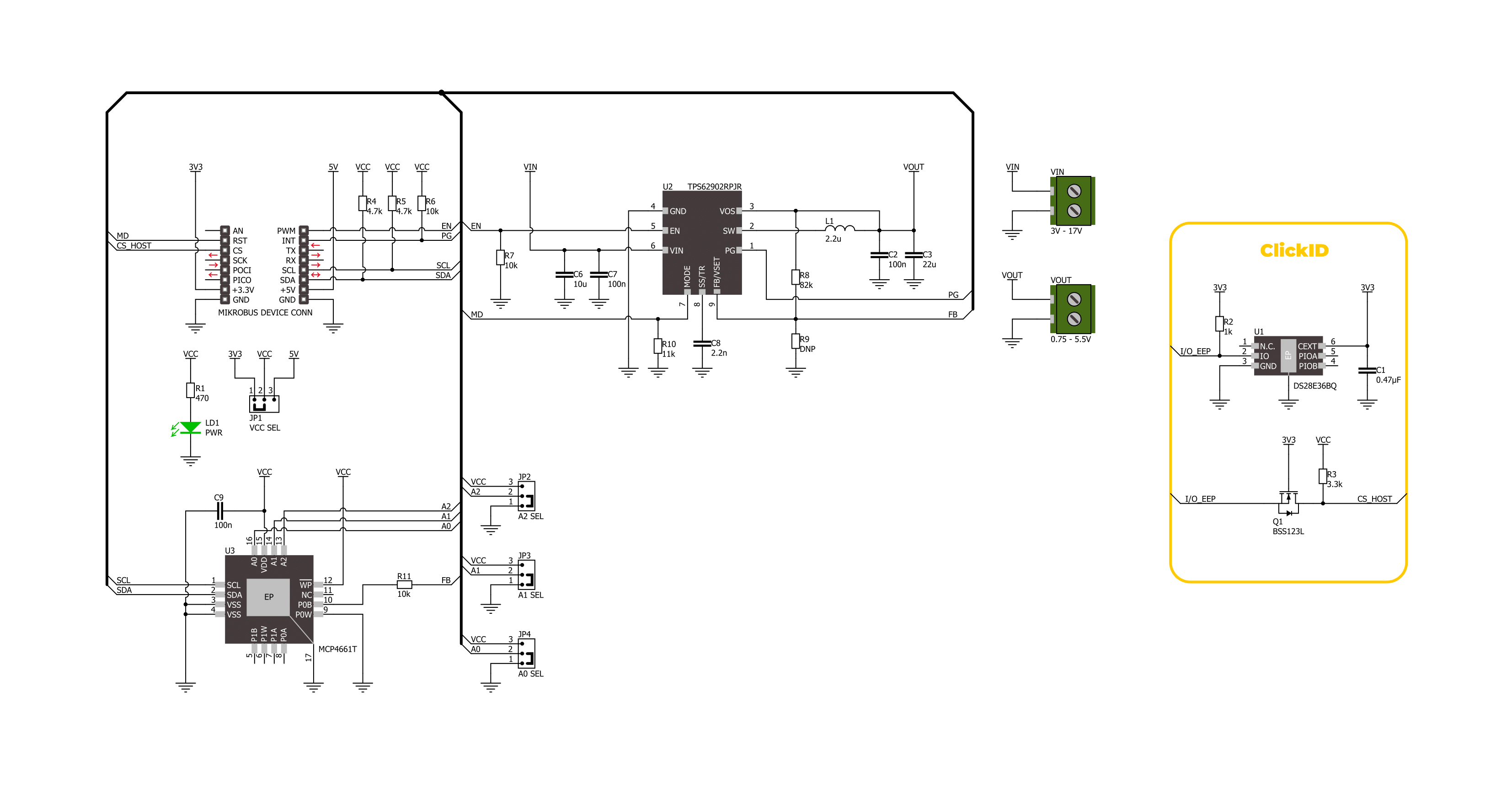
Step Down 12 Click is based on the TPS62902, a synchronous step-down DC-DC converter from Texas Instruments. This converter uses the DCS-Control topology, an advanced control architecture that merges the strengths of hysteretic, voltage mode, and current mode control. DCS-Control enables rapid response to output voltage changes by sending feedback to a fast comparator stage, ensuring constant switching frequency under stable conditions and fast adaptability during dynamic load changes. This Click board™ accommodates a wide input voltage range from 3V to 17V through its VIN terminal, making it suitable for various standard power sources, including 12V supply lines, single or multiple Li-Ion cells, and 5V or 3.3V rails. It is suitable for numerous use cases, including factory automation, building automation, data center systems, enterprise computing, motor
drive applications, and beyond. It is designed with precision and delivers an output voltage accuracy of ±1% due to its DCS-Control-based regulation. Additionally, the TPS62902 enters power save mode during light loads to maximize efficiency, backed by a low quiescent current of just 4µA, ideal for energy-conscious applications. This Click board™ integrates the MCP4661, enabling the host MCU to configure 16 fixed output voltages on the VOUT terminal, adjustable from 0.7V to 5.5V. The MCP4661 communicates through a 2-wire I2C interface that supports clock speeds up to 3.4MHz, with I2C addresses adjustable via the onboard ADDR SEL jumpers. The MD pin allows users to select the TPS62902’s operational mode, enabling flexible configuration. This pin offers options for fixed PWM or automatic PFM/PWM mode with AEE functionality and settings for switching frequency,
internal/external feedback, output discharge, and PFM/PWM selection. The EN pin functions as the converter’s enable control, while the PG (Power Good) pin is an open-drain signal to confirm if the output voltage has reached its target. It also indicates when the device is turned off due to undervoltage lockout (UVLO) or thermal shutdown, enhancing system protection and operational feedback. This Click board™ can operate with either 3.3V or 5V logic voltage levels selected via the VCC SEL jumper. This way, both 3.3V and 5V capable MCUs can use the communication lines properly. Also, this Click board™ comes equipped with a library containing easy-to-use functions and an example code that can be used as a reference for further development.

Features overview
Development board
Nucleo 32 with STM32F031K6 MCU board provides an affordable and flexible platform for experimenting with STM32 microcontrollers in 32-pin packages. Featuring Arduino™ Nano connectivity, it allows easy expansion with specialized shields, while being mbed-enabled for seamless integration with online resources. The
board includes an on-board ST-LINK/V2-1 debugger/programmer, supporting USB reenumeration with three interfaces: Virtual Com port, mass storage, and debug port. It offers a flexible power supply through either USB VBUS or an external source. Additionally, it includes three LEDs (LD1 for USB communication, LD2 for power,
and LD3 as a user LED) and a reset push button. The STM32 Nucleo-32 board is supported by various Integrated Development Environments (IDEs) such as IAR™, Keil®, and GCC-based IDEs like AC6 SW4STM32, making it a versatile tool for developers.

Microcontroller Overview
MCU Card / MCU

Architecture
ARM Cortex-M0
MCU Memory (KB)
32
Silicon Vendor
STMicroelectronics
Pin count
32
RAM (Bytes)
4096
You complete me!
Accessories
Click Shield for Nucleo-32 is the perfect way to expand your development board's functionalities with STM32 Nucleo-32 pinout. The Click Shield for Nucleo-32 provides two mikroBUS™ sockets to add any functionality from our ever-growing range of Click boards™. We are fully stocked with everything, from sensors and WiFi transceivers to motor control and audio amplifiers. The Click Shield for Nucleo-32 is compatible with the STM32 Nucleo-32 board, providing an affordable and flexible way for users to try out new ideas and quickly create prototypes with any STM32 microcontrollers, choosing from the various combinations of performance, power consumption, and features. The STM32 Nucleo-32 boards do not require any separate probe as they integrate the ST-LINK/V2-1 debugger/programmer and come with the STM32 comprehensive software HAL library and various packaged software examples. This development platform provides users with an effortless and common way to combine the STM32 Nucleo-32 footprint compatible board with their favorite Click boards™ in their upcoming projects.

Used MCU Pins
mikroBUS™ mapper
Take a closer look
Click board™ Schematic
Step by step
Project assembly

Start by selecting your development board and Click board™. Begin with the Nucleo 32 with STM32F031K6 MCU as your development board.


Software Support
Library Description
This library contains API for Step Down 12 Click driver.
Key functions:
stepdown12_get_pg_pin- This function returns the power good (PG) pin logic state.stepdown12_set_vout- This function sets the voltage output by setting the digipot wiper resistance.stepdown12_enable_device- This function enables the device by setting the EN pin to high logic state.
Open Source
Code example
The complete application code and a ready-to-use project are available through the NECTO Studio Package Manager for direct installation in the NECTO Studio. The application code can also be found on the MIKROE GitHub account.
/*!
 * @file main.c
 * @brief Step Down 12 Click example
 *
 * # Description
 * This example demonstrates the use of Step Down 12 Click board by
 * changing the output voltage every 3 seconds.
 *
 * The demo application is composed of two sections :
 *
 * ## Application Init
 * Initializes the driver and performs the Click default configuration.
 *
 * ## Application Task
 * Changes the output voltage every 3 seconds from MAX (5.5V) to MIN (1.05V) in steps of 0.5V
 * and displays the currently set voltage output value on the USB UART. It also monitors
 * the power good fault indication.
 *
 * @author Stefan Filipovic
 *
 */

#include "board.h"
#include "log.h"
#include "stepdown12.h"

static stepdown12_t stepdown12;
static log_t logger;

void application_init ( void )
{
    log_cfg_t log_cfg;  /**< Logger config object. */
    stepdown12_cfg_t stepdown12_cfg;  /**< Click config object. */

    /**
     * Logger initialization.
     * Default baud rate: 115200
     * Default log level: LOG_LEVEL_DEBUG
     * @note If USB_UART_RX and USB_UART_TX
     * are defined as HAL_PIN_NC, you will
     * need to define them manually for log to work.
     * See @b LOG_MAP_USB_UART macro definition for detailed explanation.
     */
    LOG_MAP_USB_UART( log_cfg );
    log_init( &logger, &log_cfg );
    log_info( &logger, " Application Init " );

    // Click initialization.
    stepdown12_cfg_setup( &stepdown12_cfg );
    STEPDOWN12_MAP_MIKROBUS( stepdown12_cfg, MIKROBUS_1 );
    if ( I2C_MASTER_ERROR == stepdown12_init( &stepdown12, &stepdown12_cfg ) )
    {
        log_error( &logger, " Communication init." );
        for ( ; ; );
    }

    stepdown12_default_cfg ( &stepdown12 );

    log_info( &logger, " Application Task " );
}

void application_task ( void )
{
    static float vout = STEPDOWN12_VOUT_MAX;

    if ( !stepdown12_get_pg_pin ( &stepdown12 ) )
    {
        log_error( &logger, " Power Good Fault - Vout is below nominal regulation\r\n" );
    }

    if ( STEPDOWN12_OK == stepdown12_set_vout ( &stepdown12, vout ) )
    {
        log_printf( &logger, " Vout: %.3f V\r\n\n", vout );
        vout -= 0.5;
        if ( vout < STEPDOWN12_VOUT_MIN )
        {
            vout = STEPDOWN12_VOUT_MAX;
        }
    }
    Delay_ms ( 1000 );
    Delay_ms ( 1000 );
    Delay_ms ( 1000 );
}

int main ( void )
{
    /* Do not remove this line or clock might not be set correctly. */
    #ifdef PREINIT_SUPPORTED
    preinit();
    #endif

    application_init( );

    for ( ; ; )
    {
        application_task( );
    }

    return 0;
}

// ------------------------------------------------------------------------ END
Additional Support
Resources
Category:Buck


