Ensure your energy is transformed with minimal loss thanks to RPL-3.0-R and PIC18F45K50
The epitome of voltage control

Published Nov 13, 2023
Click board™
Nano Power 3 Click
Dev. board
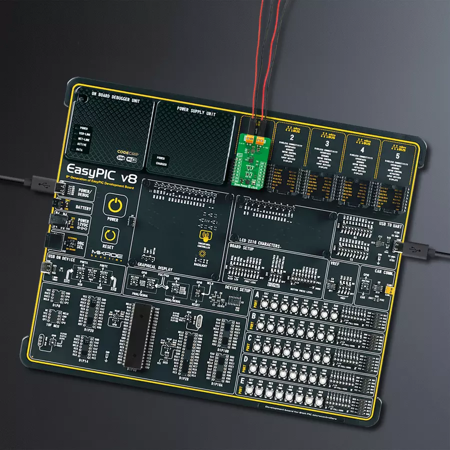
EasyPIC v8
Compiler
NECTO Studio
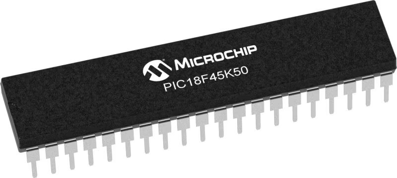
MCU
PIC18F45K50
Our outstanding buck converter solution, the pocket-sized powerhouse, transforms voltage seamlessly, providing a reliable and efficient energy source for your projects.
A
A
Hardware Overview
How does it work?
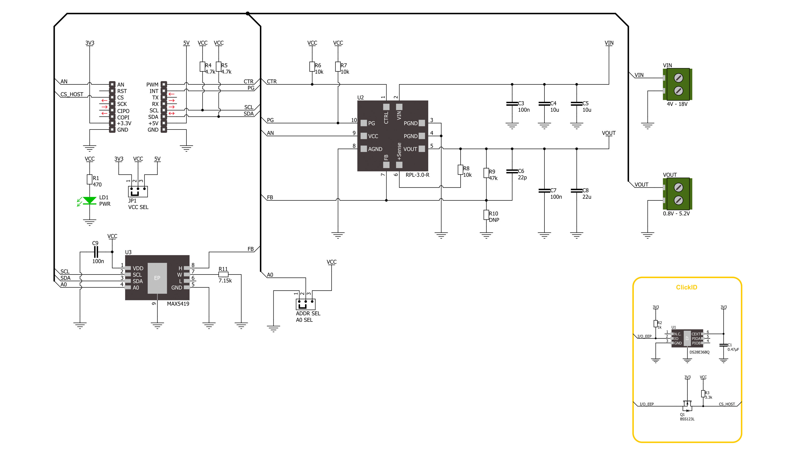
Nano Power 3 Click is based on the RPL-3.0-R, a buck converter with an integrated inductor from Recom Power. This thermally-enhanced converter uses, as input, voltage from 4 up to 18VDC, thus allowing 5V and 12V supply rails to be used. It's fully protected against continuous short circuits, output overcurrent, or over-temperature faults. To set the output voltage on the VOUT terminal, the Nano Power 3 Click uses the MAX5419, a 256-tap nonvolatile digital potentiometer from Analog Devices. This potentiometer features the power-on recall of the wiper position from nonvolatile EEPROM memory. The nominal resistance of this
potentiometer is 200kΩ, and with an onboard resistor, it makes a voltage divider that feeds the feedback input of the buck converter. You select the output voltage value by setting the resistance value on this potentiometer. Nano Power 3 Click uses a standard 2-Wire I2C interface of the MAX5419 to communicate with the host MCU, supporting Fast mode and data rates of up to 400Kbps. The I2C address can be set over the ADDR SEL jumper with 0 selected by default. In addition to the digital potentiometer control, you can also control the buck converter by turning it OFF via the CTR pin. The PG pin serves as the buck
converter Power Good condition output, which interrupts the host MCU according to meeting one of the overvoltage or undervoltage thresholds and sink current capability. The buck converter's output voltage can be read over the AN pin of the mikroBUS™ socket. This Click board™ can operate with either 3.3V or 5V logic voltage levels selected via the VCC SEL jumper. This way, both 3.3V and 5V capable MCUs can use the communication lines properly. Also, this Click board™ comes equipped with a library containing easy-to-use functions and an example code that can be used as a reference for further development.

Features overview
Development board
EasyPIC v8 is a development board specially designed for the needs of rapid development of embedded applications. It supports many high pin count 8-bit PIC microcontrollers from Microchip, regardless of their number of pins, and a broad set of unique functions, such as the first-ever embedded debugger/programmer. The development board is well organized and designed so that the end-user has all the necessary elements, such as switches, buttons, indicators, connectors, and others, in one place. Thanks to innovative manufacturing technology, EasyPIC v8 provides a fluid and immersive working experience, allowing access anywhere and under any
circumstances at any time. Each part of the EasyPIC v8 development board contains the components necessary for the most efficient operation of the same board. In addition to the advanced integrated CODEGRIP programmer/debugger module, which offers many valuable programming/debugging options and seamless integration with the Mikroe software environment, the board also includes a clean and regulated power supply module for the development board. It can use a wide range of external power sources, including a battery, an external 12V power supply, and a power source via the USB Type-C (USB-C) connector.
Communication options such as USB-UART, USB DEVICE, and CAN are also included, including the well-established mikroBUS™ standard, two display options (graphical and character-based LCD), and several different DIP sockets. These sockets cover a wide range of 8-bit PIC MCUs, from the smallest PIC MCU devices with only eight up to forty pins. EasyPIC v8 is an integral part of the Mikroe ecosystem for rapid development. Natively supported by Mikroe software tools, it covers many aspects of prototyping and development thanks to a considerable number of different Click boards™ (over a thousand boards), the number of which is growing every day.

Microcontroller Overview
MCU Card / MCU
Architecture
PIC
MCU Memory (KB)
32
Silicon Vendor
Microchip
Pin count
40
RAM (Bytes)
2048
Used MCU Pins
mikroBUS™ mapper
Take a closer look
Click board™ Schematic
Step by step
Project assembly

Start by selecting your development board and Click board™. Begin with the EasyPIC v8 as your development board.


Software Support
Library Description
This library contains API for Nano Power 3 Click driver.
Key functions:
nanopower3_set_ctr_pin- Nano Power 3 set CTRL pin state function.nanopower3_set_wiper_pos- Nano Power 3 set wiper position function.nanopower3_set_voltage- Nano Power 3 set output voltage function.
Open Source
Code example
The complete application code and a ready-to-use project are available through the NECTO Studio Package Manager for direct installation in the NECTO Studio. The application code can also be found on the MIKROE GitHub account.
/*!
 * @file main.c
 * @brief Nano Power 3 Click example
 *
 * # Description
 * This library contains API for the Nano Power 3 Click driver.
 * This driver provides the functions to set the output voltage treshold.
 *
 * The demo application is composed of two sections :
 *
 * ## Application Init
 * Initialization of I2C module and log UART.
 * After driver initialization, default settings sets output voltage to 1 V.
 *
 * ## Application Task
 * This example demonstrates the use of the Nano Power 3 Click board™ by changing
 * output voltage every 5 seconds starting from 1 V up to 4.5 V.
 *
 * @author Stefan Ilic
 *
 */

#include "board.h"
#include "log.h"
#include "nanopower3.h"

static nanopower3_t nanopower3;
static log_t logger;

/**
 * @brief Output level printing function.
 * @details This function is used to log value of the selected voltage to UART terminal.
 * @param[in] sel_level : Selected voltage level.
 * @return Nothing.
 * @note None.
 */
static void print_selected_output_level ( uint8_t sel_level );

void application_init ( void )
{
    log_cfg_t log_cfg;  /**< Logger config object. */
    nanopower3_cfg_t nanopower3_cfg;  /**< Click config object. */

    /**
     * Logger initialization.
     * Default baud rate: 115200
     * Default log level: LOG_LEVEL_DEBUG
     * @note If USB_UART_RX and USB_UART_TX
     * are defined as HAL_PIN_NC, you will
     * need to define them manually for log to work.
     * See @b LOG_MAP_USB_UART macro definition for detailed explanation.
     */
    LOG_MAP_USB_UART( log_cfg );
    log_init( &logger, &log_cfg );
    log_info( &logger, " Application Init " );

    // Click initialization.
    nanopower3_cfg_setup( &nanopower3_cfg );
    NANOPOWER3_MAP_MIKROBUS( nanopower3_cfg, MIKROBUS_1 );
    if ( I2C_MASTER_ERROR == nanopower3_init( &nanopower3, &nanopower3_cfg ) )
    {
        log_error( &logger, " Communication init." );
        for ( ; ; );
    }

    if ( NANOPOWER3_ERROR == nanopower3_default_cfg ( &nanopower3 ) )
    {
        log_error( &logger, " Default configuration." );
        for ( ; ; );
    }

    log_info( &logger, " Application Task " );
}

void application_task ( void )
{
    for ( uint8_t n_cnt = NANOPOWER3_1V_OUT_VOLTAGE; n_cnt <= NANOPOWER3_4V5_OUT_VOLTAGE; n_cnt++ )
    {
        nanopower3_set_voltage( &nanopower3, n_cnt );
        log_printf( &logger, " Selected output is:" );
        print_selected_output_level ( n_cnt );
        Delay_ms ( 1000 );
        Delay_ms ( 1000 );
        Delay_ms ( 1000 );
        Delay_ms ( 1000 );
        Delay_ms ( 1000 );
    }
}

int main ( void )
{
    /* Do not remove this line or clock might not be set correctly. */
    #ifdef PREINIT_SUPPORTED
    preinit();
    #endif

    application_init( );

    for ( ; ; )
    {
        application_task( );
    }

    return 0;
}

static void print_selected_output_level ( uint8_t sel_level )
{
    switch ( sel_level )
    {
        case ( NANOPOWER3_1V_OUT_VOLTAGE ):
        {
            log_printf( &logger, " 1V\r\n" );
            break;
        }
        case ( NANOPOWER3_1V2_OUT_VOLTAGE ):
        {
            log_printf( &logger, " 1.2V\r\n" );
            break;
        }
        case ( NANOPOWER3_1V5_OUT_VOLTAGE ):
        {
            log_printf( &logger, " 1.5V\r\n" );
            break;
        }
        case ( NANOPOWER3_1V8_OUT_VOLTAGE ):
        {
            log_printf( &logger, " 1.8V\r\n" );
            break;
        }
        case ( NANOPOWER3_2V_OUT_VOLTAGE ):
        {
            log_printf( &logger, " 2V\r\n" );
            break;
        }
        case ( NANOPOWER3_2V5_OUT_VOLTAGE ):
        {
            log_printf( &logger, " 2.5V\r\n" );
            break;
        }
        case ( NANOPOWER3_3V_OUT_VOLTAGE ):
        {
            log_printf( &logger, " 3V\r\n" );
            break;
        }
        case ( NANOPOWER3_3V3_OUT_VOLTAGE ):
        {
            log_printf( &logger, " 3.3V\r\n" );
            break;
        }
        case ( NANOPOWER3_3V5_OUT_VOLTAGE ):
        {
            log_printf( &logger, " 3.5V\r\n" );
            break;
        }
        case ( NANOPOWER3_4V_OUT_VOLTAGE ):
        {
            log_printf( &logger, " 4V\r\n" );
            break;
        }
        case ( NANOPOWER3_4V5_OUT_VOLTAGE ):
        {
            log_printf( &logger, " 4.5V\r\n" );
            break;
        }
        default:
        {
            log_printf( &logger, " ERROR\r\n" );
        }
    }
}

// ------------------------------------------------------------------------ END


