Enhance energy-efficient home automation systems with 3006.2112 combined with STM32F302VC
Red LED tactile switch: Your shortcut to effortless control
Published Jul 22, 2025
Click board™
Button R Click
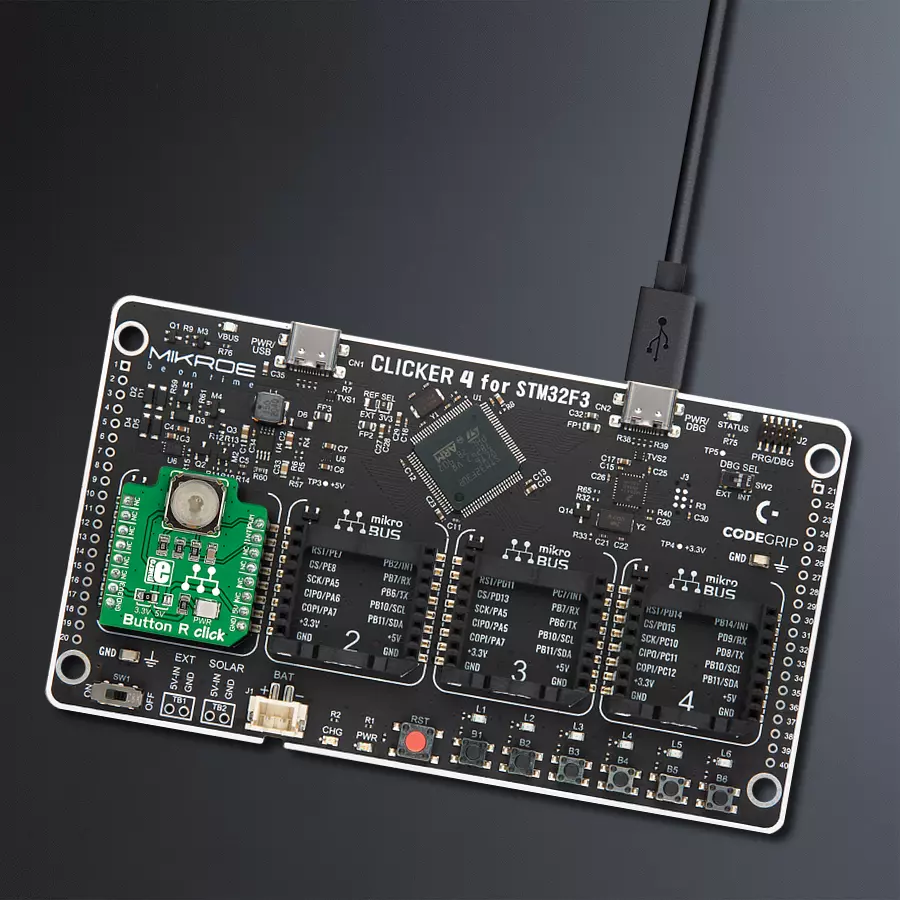
Dev. board
CLICKER 4 for STM32F302VCT6
Compiler
NECTO Studio
MCU
STM32F302VC
Enhance the usability of your project by using the red-ringed button as a universal action marker, allowing users to easily identify and perform essential tasks
A
A
Hardware Overview
How does it work?
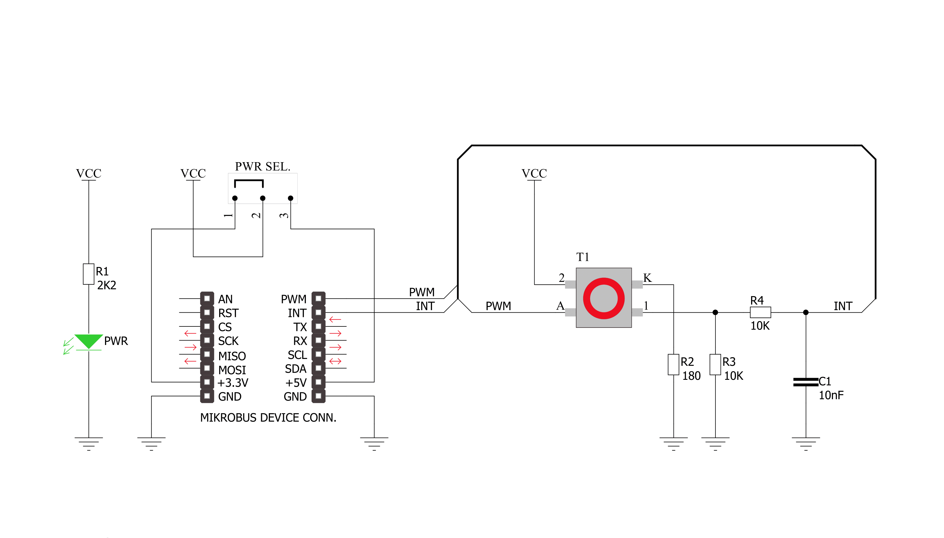
Button R Click is based on the 3006.2112, a tactile switch with integrated independent red LED from Marquardt. The tactile switch has a debounce circuit to eliminate the ripple signal and provide a clean transition at its output and is pulled down. The round transparent button of the tactile switch is 6.8mm in diameter and has a red LED background light. This LED can be programmed as feedback to the user to make a visual expression of knowing the contact has been
made. Since the backlight LED is controlled independently, it can be programmed in different patterns, such as varying light levels, light intensity, or blinking rate on subsequent button presses, thus giving additional feedback to the end user. The tactile button of this Click board™ sends an interrupt signal to the host MCU using the INT pin of the mikroBUS™ socket. The host MCU can control the integrated red LED using the PWM pin of the mikroBUS™ socket. The Pulse
Width Modulation (PWM) lets you program this LED using various blinking patterns and light intensity. This Click board™ can operate with either 3.3V or 5V logic voltage levels selected via an onboard jumper. This way, both 3.3V and 5V capable MCUs can use the communication lines properly. However, the Click board™ comes equipped with a library containing easy-to-use functions and an example code that can be used as a reference for further development.

Features overview
Development board
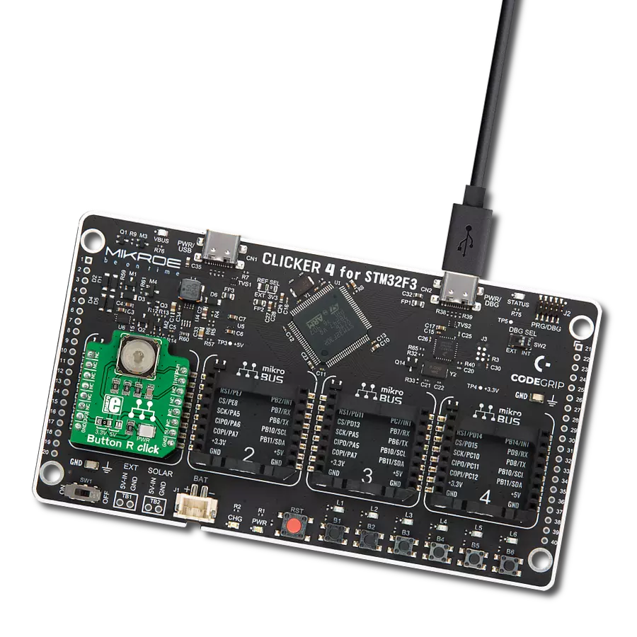
Clicker 4 for STM32F3 is a compact development board designed as a complete solution, you can use it to quickly build your own gadgets with unique functionalities. Featuring a STM32F302VCT6, four mikroBUS™ sockets for Click boards™ connectivity, power managment, and more, it represents a perfect solution for the rapid development of many different types of applications. At its core, there is a STM32F302VCT6 MCU, a powerful microcontroller by STMicroelectronics, based on the high-
performance Arm® Cortex®-M4 32-bit processor core operating at up to 168 MHz frequency. It provides sufficient processing power for the most demanding tasks, allowing Clicker 4 to adapt to any specific application requirements. Besides two 1x20 pin headers, four improved mikroBUS™ sockets represent the most distinctive connectivity feature, allowing access to a huge base of Click boards™, growing on a daily basis. Each section of Clicker 4 is clearly marked, offering an intuitive and clean interface. This makes working with the development
board much simpler and thus, faster. The usability of Clicker 4 doesn’t end with its ability to accelerate the prototyping and application development stages: it is designed as a complete solution which can be implemented directly into any project, with no additional hardware modifications required. Four mounting holes [4.2mm/0.165”] at all four corners allow simple installation by using mounting screws. For most applications, a nice stylish casing is all that is needed to turn the Clicker 4 development board into a fully functional, custom design.

Microcontroller Overview
MCU Card / MCU

Architecture
ARM Cortex-M4
MCU Memory (KB)
256
Silicon Vendor
STMicroelectronics
Pin count
100
RAM (Bytes)
40960
Used MCU Pins
mikroBUS™ mapper
Take a closer look
Click board™ Schematic
Step by step
Project assembly

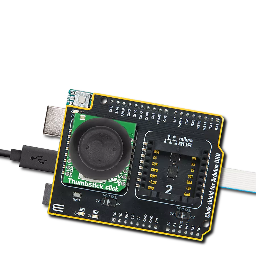
Start by selecting your development board and Click board™. Begin with the CLICKER 4 for STM32F302VCT6 as your development board.


Track your results in real time
Application Output
1. Application Output - In Debug mode, the 'Application Output' window enables real-time data monitoring, offering direct insight into execution results. Ensure proper data display by configuring the environment correctly using the provided tutorial.

2. UART Terminal - Use the UART Terminal to monitor data transmission via a USB to UART converter, allowing direct communication between the Click board™ and your development system. Configure the baud rate and other serial settings according to your project's requirements to ensure proper functionality. For step-by-step setup instructions, refer to the provided tutorial.

3. Plot Output - The Plot feature offers a powerful way to visualize real-time sensor data, enabling trend analysis, debugging, and comparison of multiple data points. To set it up correctly, follow the provided tutorial, which includes a step-by-step example of using the Plot feature to display Click board™ readings. To use the Plot feature in your code, use the function: plot(*insert_graph_name*, variable_name);. This is a general format, and it is up to the user to replace 'insert_graph_name' with the actual graph name and 'variable_name' with the parameter to be displayed.

Software Support
Library Description
This library contains API for Button R Click driver.
Key functions:
buttonr_pwm_stop- This function stops the PWM moudle output.buttonr_pwm_start- This function starts the PWM moudle output.buttonr_get_button_state- This function reads the digital signal from the INT pin which tells us whether the button has been pressed or not.
Open Source
Code example
The complete application code and a ready-to-use project are available through the NECTO Studio Package Manager for direct installation in the NECTO Studio. The application code can also be found on the MIKROE GitHub account.
/*!
 * @file main.c
 * @brief ButtonR Click example
 *
 * # Description
 * This library contains API for Button R Click driver.
 * One library is used for every single one of them.
 * They are simple touch detectors that send a pressed/released
 * signal and receive a PWM output which controls the backlight on the button.
 *
 * The demo application is composed of two sections :
 *
 * ## Application Init
 * This function initializes and configures the logger and Click modules.
 *
 * ## Application Task
 * This example first increases the backlight on the button and then decreases the intensity of backlight. When the button is pressed,
 * reports the event in the console using UART communication.
 *
 * @author Nikola Peric
 *
 */

#include "board.h"
#include "log.h"
#include "buttonr.h"

static buttonr_t buttonr;
static log_t logger;

void application_init ( void )
{
    log_cfg_t log_cfg;          /**< Logger config object. */
    buttonr_cfg_t buttonr_cfg;  /**< Click config object. */

    /**
     * Logger initialization.
     * Default baud rate: 115200
     * Default log level: LOG_LEVEL_DEBUG
     * @note If USB_UART_RX and USB_UART_TX
     * are defined as HAL_PIN_NC, you will
     * need to define them manually for log to work.
     * See @b LOG_MAP_USB_UART macro definition for detailed explanation.
     */
    LOG_MAP_USB_UART( log_cfg );
    log_init( &logger, &log_cfg );
    log_info( &logger, " Application Init " );

    // Click initialization.

    buttonr_cfg_setup( &buttonr_cfg );
    BUTTONR_MAP_MIKROBUS( buttonr_cfg, MIKROBUS_1 );
    err_t init_flag  = buttonr_init( &buttonr, &buttonr_cfg );
    if ( PWM_ERROR == init_flag )
    {
        log_error( &logger, " Application Init Error. " );
        log_info( &logger, " Please, run program again... " );

        for ( ; ; );
    }
    Delay_ms ( 500 );

    buttonr_set_duty_cycle ( &buttonr, 0.0 );
    buttonr_pwm_start( &buttonr );

    log_info( &logger, " Application Task " );
}

void application_task ( void )
{
    static float duty_cycle;
    static uint8_t button_state;
    static uint8_t button_state_old;

    button_state = buttonr_get_button_state( &buttonr );

    if ( button_state && ( button_state != button_state_old ) )
    {
        log_printf( &logger, " <-- Button pressed --> \r\n" );
        for ( uint8_t n_cnt = 1; n_cnt <= 100; n_cnt++  )
        {
            duty_cycle = ( float ) n_cnt ;
            duty_cycle /= 100;
            buttonr_set_duty_cycle( &buttonr, duty_cycle );
            Delay_ms ( 10 );
        }
        button_state_old = button_state;
    }
    else if ( !button_state && ( button_state != button_state_old ) )
    {
        for ( uint8_t n_cnt = 100; n_cnt > 0; n_cnt-- )
        {
            duty_cycle = ( float ) n_cnt ;
            duty_cycle /= 100;
            buttonr_set_duty_cycle( &buttonr,  duty_cycle );
            Delay_ms ( 10 );
        }
        button_state_old = button_state;
    }
}

int main ( void )
{
    /* Do not remove this line or clock might not be set correctly. */
    #ifdef PREINIT_SUPPORTED
    preinit();
    #endif

    application_init( );

    for ( ; ; )
    {
        application_task( );
    }

    return 0;
}

// ------------------------------------------------------------------------ END
Additional Support
Resources
Category:Pushbutton/Switches