Take control of your environment with 3SP CO 1000 and PIC32MZ2048EFM144
Safeguarding lives with intelligent gas detection!
Published Jul 22, 2025
Click board™
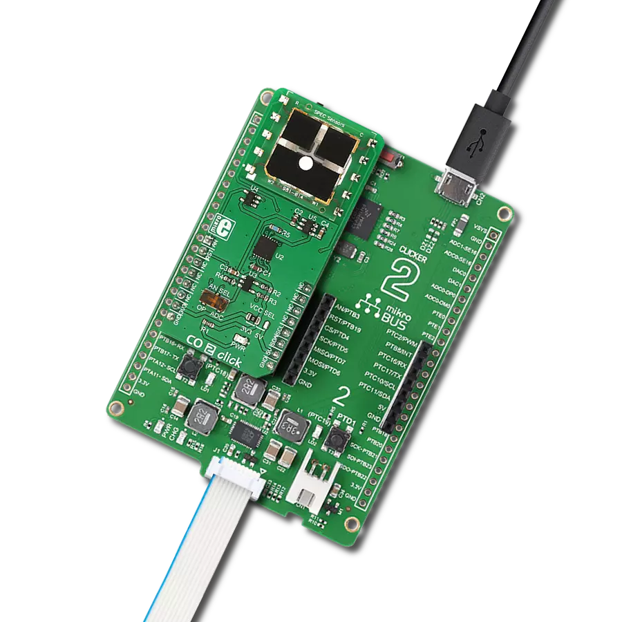
CO 2 Click
Dev. board
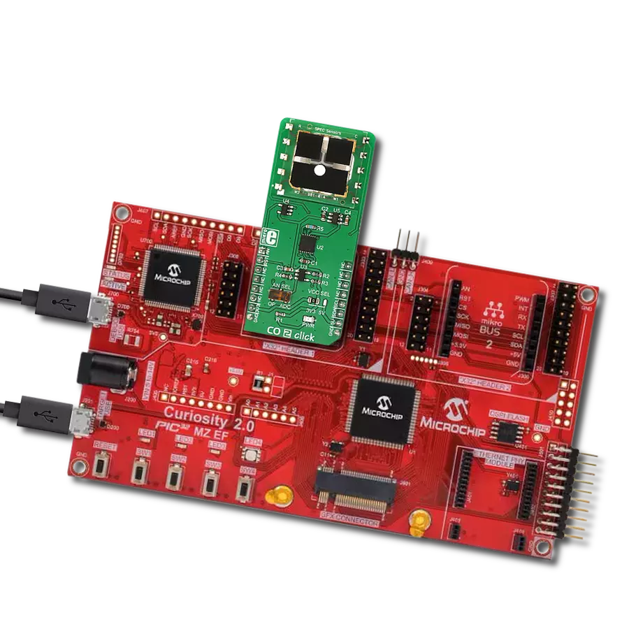
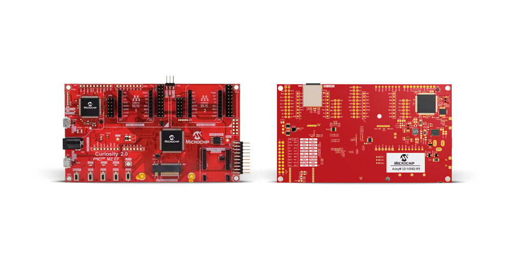
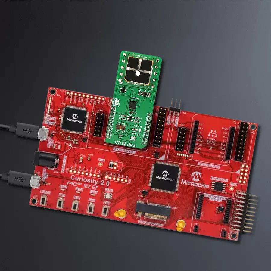
Curiosity PIC32MZ EF 2.0 Development Board
Compiler
NECTO Studio
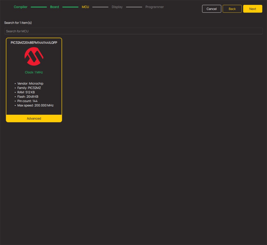
MCU
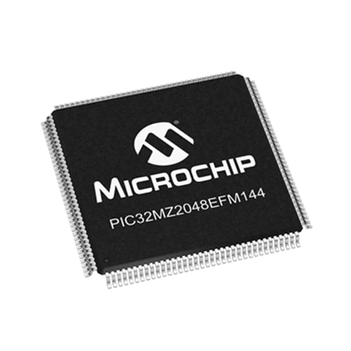
PIC32MZ2048EFM144
Our CO gas detection solution stands as a reliable sentinel, providing immediate alerts and real-time data to protect individuals and spaces from the dangers of carbon monoxide
A
A
Hardware Overview
How does it work?
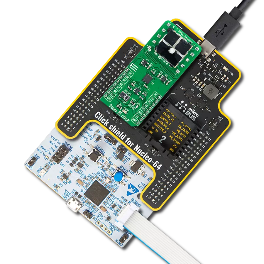
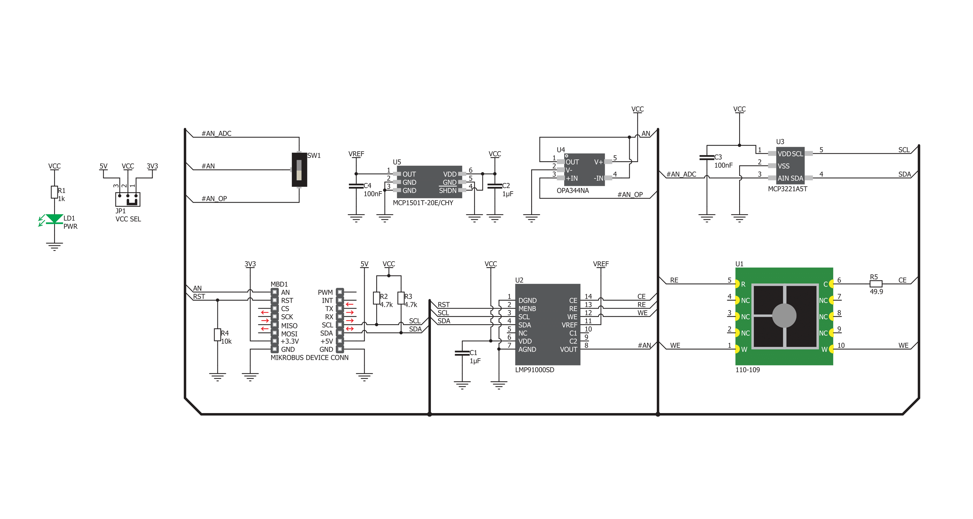
CO 2 Click is based on the 3SP CO 1000, a carbon monoxide (CO) gas sensor from SPEC Sensors, which can sense CO concentration up to 1000ppm. The sensor has a very short response time; however, the longer it is exposed to a particular gas, the more accurate data it can provide. This is especially true when calibration is performed. The sensor is highly sensitive to small dust particles, condensed water, and other impurities, which might prevent gas from reaching the sensor. It is advised to protect the sensor when used in critical applications. In ideal conditions, the lifetime of this sensor is indefinite. Still, in a real-life application, the expected operating life is over five years (10 years at a temperature of 23 ± 3 ˚C and humidity of 40 ± 10% RH). Although very reliable and accurate, this sensor is also great for building relative gas sensing applications. For example, it can detect an increased level of CO gas, which is very hard to detect due to being tasteless, odorless, and colorless. However, when developing applications for the absolute gas concentration, the sensor must be calibrated, and the measurement data needs to be compensated. Factors such as humidity and temperature can affect measurements, the sensor-reaction curve to a specific measured gas (carbon monoxide in this case) is not completely linear, and other gases might affect the measurement (cross-sensitivity to
other gases). For this reason, a range of calibration routines has to be done in the working environment conditions to calculate the absolute gas concentration. CO 2 click uses the LMP91000, a configurable AFE potentiostat IC for low-power chemical sensing applications, from Texas Instruments. It provides the complete sensor solution, generating the output voltage proportional to the sensor current. A trans-impedance amplifier (TIA) with a programmable gain converts the current through the sensor, covering the range from 5μA to 750 μA, depending on the sensor used. The voltage between the referent electrode (RE) and the working electrode (WE) is constant, with the bias set by the variable bias circuitry. This type of sensor performs best when a fixed bias voltage is applied. The sensor manufacturer recommends a 200mV fixed bias for the sensor on this Click board™. The bias voltage and the TIA gain can be set via the I2C registers. In addition, there is an embedded thermal sensor in the AFE IC, which, if needed, can be used for the result compensation. It is available via the VOUT pin as the analog voltage value with respect to GND. The Click board™ has two additional ICs onboard. The first is the MCP3221, a 12-bit successive approximation register A/D converter from Microchip. The second IC is the OPA344, a single-supply, rail-to-rail operational amplifier manufactured by Texas Instruments. It is possible
to use the onboard switch, labeled as AN SEL, to select the IC to which the VOUT pin from the LMP91000 AFE is routed. If the switch is in the ADC position, the VOUT pin will be routed to the input of the MCP3221 ADC. This allows the voltage value at the VOUT pin to be read as digital information via the I2C interface. When the switch is in the AN position, it will route the VOUT pin of the LMP91000 AFE IC to the input of the OPA344. The output of the OPA344 op-amp has a stable unity gain, acting as a buffer so that the voltage at the VOUT pin of the AFE can be sampled by the host MCU via the AN pin of the mikroBUS™. The RST pin on the mikroBUS™ is routed to the MEMB pin of the LMP91000, and it is used to enable the I2C interface section, making it possible to use more than one chip on the same I2C bus. When driven to the LOW logic level, the I2C communication is enabled, and the host device (host MCU) can issue the START condition. The RST pin should stay at the LOW during the communication. This Click board™ can operate with either 3.3V or 5V logic voltage levels selected via the VCC SEL jumper. This way, both 3.3V and 5V capable MCUs can use the communication lines properly. Also, this Click board™ comes equipped with a library containing easy-to-use functions and an example code that can be used as a reference for further development.


Features overview
Development board
The Curiosity PIC32MZ EF 2.0 Development Board (DM320209) is a fully integrated development platform built around the high-performance PIC32MZ2048EFM144 microcontroller, featuring a 200MHz CPU, 2MB of Flash, and 512KB of SRAM. It comes equipped with an onboard PKoB4 debugger that provides real-time programming and debugging capabilities, along with a Virtual COM port (VCOM) and Data Gateway Interface (DGI), eliminating the need for any external programming hardware. The board is designed for flexibility and expandability, supporting a wide range of
application development needs through its multiple interfaces and expansion options. It includes two mikroBUS™ sockets for integration with MIKROE Click board™ add-ons, two X32 audio interfaces for Bluetooth® and audio functionality, and dedicated interfaces for Ethernet, graphics, and CAN communication. The board also supports Wi-Fi™ connectivity and audio I/O via compatible Microchip daughter boards, and features an Xplained Pro extension interface for additional peripheral expansion. User interaction is enabled through configurable buttons and LEDs, while 8MB of
onboard QSPI memory provides ample space for data storage in demanding applications. Additionally, the Arduino Uno R3 compatible interface allows easy connection with a wide range of Arduino shields. With its rich set of peripherals and robust processing capabilities, the Curiosity PIC32MZ EF 2.0 Development Board is ideally suited for developing complex applications such as Bluetooth® audio systems, IoT devices, robotics platforms, CAN-based networks, and advanced graphical user interfaces.
Microcontroller Overview
MCU Card / MCU
Architecture
PIC32
MCU Memory (KB)
2048
Silicon Vendor
Microchip
Pin count
144
RAM (Bytes)
524288
Used MCU Pins
mikroBUS™ mapper
Take a closer look
Click board™ Schematic
Step by step
Project assembly
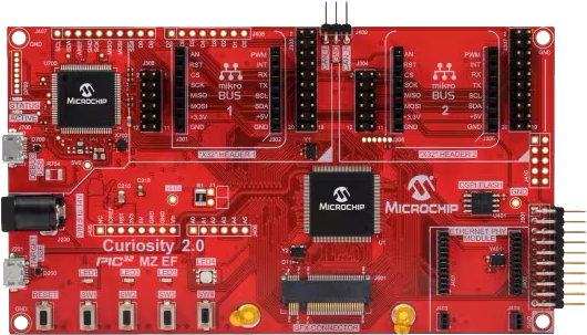
Start by selecting your development board and Click board™. Begin with the Curiosity PIC32MZ EF 2.0 Development Board as your development board.


Track your results in real time
Application Output
1. Application Output - In Debug mode, the 'Application Output' window enables real-time data monitoring, offering direct insight into execution results. Ensure proper data display by configuring the environment correctly using the provided tutorial.

2. UART Terminal - Use the UART Terminal to monitor data transmission via a USB to UART converter, allowing direct communication between the Click board™ and your development system. Configure the baud rate and other serial settings according to your project's requirements to ensure proper functionality. For step-by-step setup instructions, refer to the provided tutorial.

3. Plot Output - The Plot feature offers a powerful way to visualize real-time sensor data, enabling trend analysis, debugging, and comparison of multiple data points. To set it up correctly, follow the provided tutorial, which includes a step-by-step example of using the Plot feature to display Click board™ readings. To use the Plot feature in your code, use the function: plot(*insert_graph_name*, variable_name);. This is a general format, and it is up to the user to replace 'insert_graph_name' with the actual graph name and 'variable_name' with the parameter to be displayed.

Software Support
Library Description
This library contains API for CO 2 Click driver.
Key functions:
co2_read_adc- This function reads the converted data (CO) from the 12-bit AD converterco2_enable- This function puts the device to enabled or to disabled stateco2_get_co2_ppm- This function reads the CO converted data and calculates this value to the ppm
Open Source
Code example
The complete application code and a ready-to-use project are available through the NECTO Studio Package Manager for direct installation in the NECTO Studio. The application code can also be found on the MIKROE GitHub account.
/*!
 * \file
 * \brief CO2 Click example
 *
 * # Description
 * This application enables usage of very accurate CO sensor.
 *
 * The demo application is composed of two sections :
 *
 * ## Application Init
 * Initializes I2C interface and performs the device configuration for properly working.
 *
 * ## Application Task
 * Gets CO (Carbon Monoxide) data as ppm value every 300 miliseconds.
 * Results will be logged on UART. The CO value range is from 0 to 1000 ppm.
 *
 *
 * \author MikroE Team
 *
 */
// ------------------------------------------------------------------- INCLUDES

#include "board.h"
#include "log.h"
#include "co2.h"

// ------------------------------------------------------------------ VARIABLES

static co2_t co2;
static log_t logger;

// ------------------------------------------------------ APPLICATION FUNCTIONS

void application_init ( void )
{
    log_cfg_t log_cfg;
    co2_cfg_t cfg;
    uint8_t temp_w;

    /**
     * Logger initialization.
     * Default baud rate: 115200
     * Default log level: LOG_LEVEL_DEBUG
     * @note If USB_UART_RX and USB_UART_TX
     * are defined as HAL_PIN_NC, you will
     * need to define them manually for log to work.
     * See @b LOG_MAP_USB_UART macro definition for detailed explanation.
     */
    LOG_MAP_USB_UART( log_cfg );
    log_init( &logger, &log_cfg );
    log_info( &logger, "---- Application Init ----" );

    //  Click initialization.

    co2_cfg_setup( &cfg );
    CO2_MAP_MIKROBUS( cfg, MIKROBUS_1 );
    co2_init( &co2, &cfg );

    Delay_ms ( 500 );

    temp_w = CO2_WRITE_MODE;
    co2_generic_write( &co2, CO2_LOCK_REG, &temp_w, 1 );
    temp_w = CO2_STANDBY_MODE;
    co2_generic_write( &co2, CO2_MODECN_REG, &temp_w, 1 );
    temp_w = CO2_3500_OHM_TIA_RES | CO2_100_OHM_LOAD_RES;
    co2_generic_write( &co2, CO2_TIACN_REG, &temp_w, 1 );
    temp_w = CO2_VREF_EXT | CO2_50_PERCENTS_INT_ZERO | CO2_BIAS_POL_NEGATIVE | CO2_0_PERCENTS_BIAS;
    co2_generic_write( &co2, CO2_REFCN_REG, &temp_w, 1 );

    log_printf( &logger, "CO 2 is initialized\r\n\r\n" );
    Delay_ms ( 1000 );
}

void application_task ( void )
{
    float co2_value;

    co2_wait_i2c_ready( &co2 );
    co2_get_co2_ppm( &co2, &co2_value );

    log_printf( &logger, "CO : %.2f ppm\r\n", co2_value );
    Delay_ms ( 300 );
}

int main ( void )
{
    /* Do not remove this line or clock might not be set correctly. */
    #ifdef PREINIT_SUPPORTED
    preinit();
    #endif

    application_init( );

    for ( ; ; )
    {
        application_task( );
    }

    return 0;
}


// ------------------------------------------------------------------------ END