Attain unparalleled accuracy in measuring AC or DC currents using PIC32MX695F512L and ACS770
Transforming applications with current sensing

Published Aug 12, 2023
Click board™
Hall Current 7 Click
Dev. board
Fusion for PIC32 v8
Compiler
NECTO Studio
MCU
PIC32MX695F512L
Navigate complex current flows confidently with our Hall-effect sensing solution, enabling you to understand current behavior and make informed adjustments to enhance system efficiency
A
A
Hardware Overview
How does it work?
Hall Current 7 Click is based on the ACS770, a thermally enhanced, fully integrated, Hall effect-based high precision linear current sensor with 100µΩ current conductor from Allegro MicroSystems. This Hall-effect current sensor eliminates the need for a sense-resistor. The current flows directly into the integrated conductor, generating a magnetic field that will be measured. As current flows in its integrated conductor, an integrated low-hysteresis core concentrates the magnetic field that is then sensed by the Hall element with a typical accuracy of ±1% and 120 kHz bandwidth. This core also acts as a magnetic shield, rejecting external stray fields. The integrated conductor has 100μΩ resistance, providing ultralow-power loss. The copper
conductor's thickness allows the device's survival at high overcurrent conditions. The terminals of the conductive path are electrically isolated from the signal leads. This enables the ACS770 to be used in applications requiring electrical isolation without optoisolators or other costly isolation techniques. The ACS770 outputs an analog signal that varies linearly with the bidirectional AC or DC primary sampled current. The analog signal is then brought to the analog-to-digital converter (ADC) that converts the output signal from the ACS770 into a digital value, available over the I2C interface. Hall Current 7 Click communicates with MCU through the MCP3221, a successive approximation A/D converter with a 12-bit resolution from Microchip, using a 2-wire I2C compatible interface. This
device provides one single-ended input with low power consumption, a low maximum conversion current, and a Standby current of 250 μA and 1 μA, respectively. Data can be transferred at 100kbit/s in the Standard and 400 kbit/s in the Fast Mode. Also, maximum sample rates of 22.3 kSPS with the MCP3221 are possible in a Continuous-Conversion Mode with a clock rate of 400 kHz. This Click board™ can operate with either 3.3V or 5V logic voltage levels selected via the VCC SEL jumper. This way, both 3.3V and 5V capable MCUs can use the communication lines properly. Also, this Click board™ comes equipped with a library containing easy-to-use functions and an example code that can be used, as a reference, for further development.


Features overview
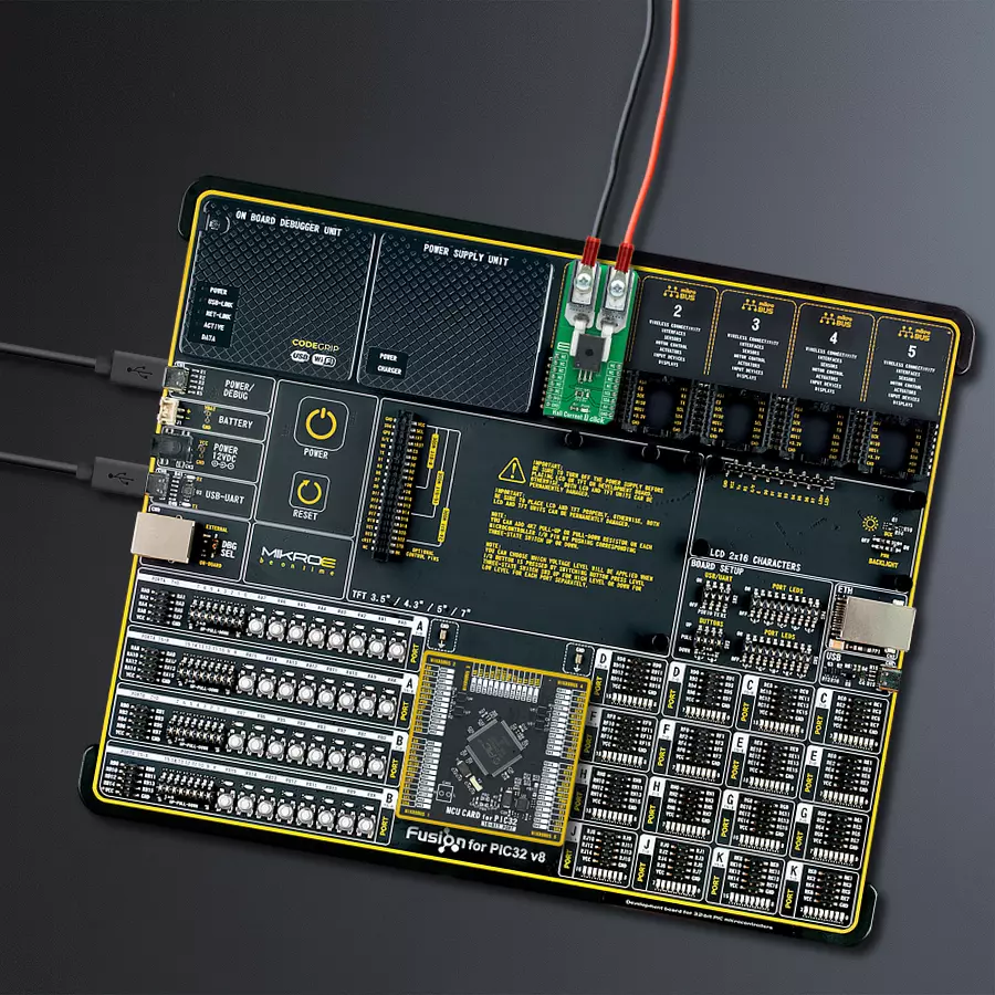
Development board
Fusion for PIC32 v8 is a development board specially designed for the needs of rapid development of embedded applications. It supports a wide range of Microchip's PIC32 microcontrollers regardless of their number of pins and a broad set of unique functions, such as the first-ever embedded debugger/programmer over WiFi. The development board is well organized and designed so that the end-user has all the necessary elements, such as switches, buttons, indicators, connectors, and others, in one place. Thanks to innovative manufacturing technology, Fusion for PIC32 v8 provides a fluid and immersive working experience, allowing access anywhere and under any circumstances at any time. Each part of the
Fusion for PIC32 v8 development board contains the components necessary for the most efficient operation of the same board. In addition to the advanced integrated CODEGRIP programmer/debugger module, which offers many valuable programming/debugging options and seamless integration with the Mikroe software environment, the board also includes a clean and regulated power supply module for the development board. It can use a wide range of external power sources, including a battery, an external 12V power supply, and a power source via the USB Type-C (USB-C) connector. Communication options such as USB-UART, USB HOST/DEVICE, CAN (on the MCU card, if
supported), and Ethernet is also included. In addition, it also has the well-established mikroBUS™ standard, a standardized socket for the MCU card (SiBRAIN standard), and two display options for the TFT board line of products and character-based LCD. Fusion for PIC32 v8 is an integral part of the Mikroe ecosystem for rapid development. Natively supported by Mikroe software tools, it covers many aspects of prototyping and development thanks to a considerable number of different Click boards™ (over a thousand boards), the number of which is growing every day.

Microcontroller Overview
MCU Card / MCU
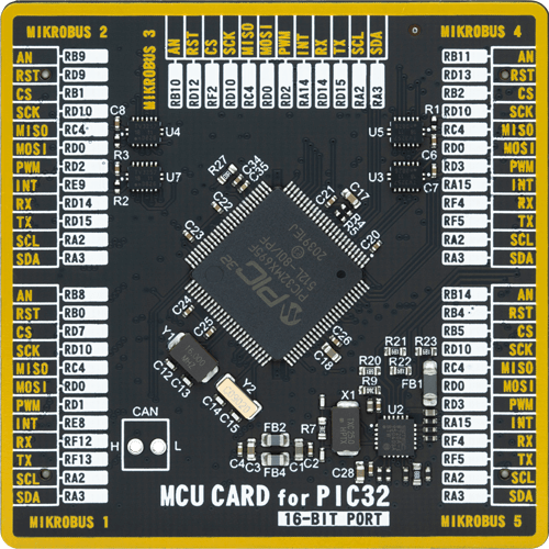
Type
8th Generation
Architecture
PIC32
MCU Memory (KB)
512
Silicon Vendor
Microchip
Pin count
100
RAM (Bytes)
131072
Used MCU Pins
mikroBUS™ mapper
Take a closer look
Click board™ Schematic

Step by step
Project assembly

Start by selecting your development board and Click board™. Begin with the Fusion for PIC32 v8 as your development board.


Track your results in real time
Application Output
1. Application Output - In Debug mode, the 'Application Output' window enables real-time data monitoring, offering direct insight into execution results. Ensure proper data display by configuring the environment correctly using the provided tutorial.

2. UART Terminal - Use the UART Terminal to monitor data transmission via a USB to UART converter, allowing direct communication between the Click board™ and your development system. Configure the baud rate and other serial settings according to your project's requirements to ensure proper functionality. For step-by-step setup instructions, refer to the provided tutorial.

3. Plot Output - The Plot feature offers a powerful way to visualize real-time sensor data, enabling trend analysis, debugging, and comparison of multiple data points. To set it up correctly, follow the provided tutorial, which includes a step-by-step example of using the Plot feature to display Click board™ readings. To use the Plot feature in your code, use the function: plot(*insert_graph_name*, variable_name);. This is a general format, and it is up to the user to replace 'insert_graph_name' with the actual graph name and 'variable_name' with the parameter to be displayed.

Software Support
Library Description
This library contains API for Hall Current 7 Click driver.
Key functions:
hallcurrent7_read_voltage- Read voltage functionhallcurrent7_calc_current- Calculate current functionhallcurrent7_avg_current- Calculate average current function
Open Source
Code example
The complete application code and a ready-to-use project are available through the NECTO Studio Package Manager for direct installation in the NECTO Studio. The application code can also be found on the MIKROE GitHub account.
/*!
 * @file main.c
 * @brief HallCurrent7 Click example
 *
 * # Description
 * This example shows the capabilities of the Hall Current 7 Click board.
 *
 * The demo application is composed of two sections :
 *
 * ## Application Init
 * Initalizes I2C driver and makes an initial log.
 *
 * ## Application Task
 * Measuring current passing through the on board Hall Effect Sensor and
 * displaying data every two seconds.
 *
 * @note
 * In order to get correct calculations user should change "v_ref"
 * value to his own power supply voltage.
 *
 * @author Stefan Ilic
 *
 */

#include "board.h"
#include "log.h"
#include "hallcurrent7.h"

static hallcurrent7_t hallcurrent7;
static log_t logger;

int16_t current;

void application_init ( void ) {
    log_cfg_t log_cfg;  /**< Logger config object. */
    hallcurrent7_cfg_t hallcurrent7_cfg;  /**< Click config object. */

    /**
     * Logger initialization.
     * Default baud rate: 115200
     * Default log level: LOG_LEVEL_DEBUG
     * @note If USB_UART_RX and USB_UART_TX
     * are defined as HAL_PIN_NC, you will
     * need to define them manually for log to work.
     * See @b LOG_MAP_USB_UART macro definition for detailed explanation.
     */
    LOG_MAP_USB_UART( log_cfg );
    log_init( &logger, &log_cfg );
    log_info( &logger, " Application Init " );

    // Click initialization.
    hallcurrent7_cfg_setup( &hallcurrent7_cfg );
    HALLCURRENT7_MAP_MIKROBUS( hallcurrent7_cfg, MIKROBUS_1 );
    err_t init_flag = hallcurrent7_init( &hallcurrent7, &hallcurrent7_cfg );
    if ( I2C_MASTER_ERROR == init_flag ) {
        log_error( &logger, " Application Init Error. " );
        log_info( &logger, " Please, run program again... " );

        for ( ; ; );
    }

    log_info( &logger, " Application Task " );
}

void application_task ( void ) {
    current = hallcurrent7_avg_current( &hallcurrent7, HALLCURRENT7_VREF_5000_mV );
    log_printf( &logger, "Current: %d mA\r\n", current );

    log_printf( &logger, "------------------------\r\n" );
    Delay_ms ( 1000 );
    Delay_ms ( 1000 );
}

int main ( void )
{
    /* Do not remove this line or clock might not be set correctly. */
    #ifdef PREINIT_SUPPORTED
    preinit();
    #endif

    application_init( );

    for ( ; ; )
    {
        application_task( );
    }

    return 0;
}

// ------------------------------------------------------------------------ END


