Contribute to the digital mapping revolution with AK09918C and STM32F410RB
Chart your path: Compass 5 Click at your service
Published Sep 27, 2023
Click board™
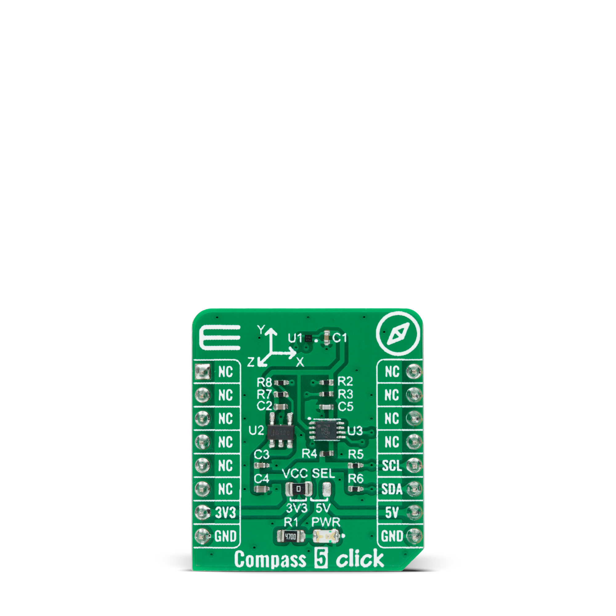
Compass 5 Click
Dev. board
UNI-DS v8
Compiler
NECTO Studio
MCU
STM32F410RB
Create highly accurate electrical compasses that provide users with dependable directional guidance
A
A
Hardware Overview
How does it work?
Compass 5 Click is based on the AK09918C, a 3-axis electronic compass with highly sensitive Hall sensor technology from AKM Semiconductor. This I2C configurable electronic compass incorporates magnetic sensors for detecting terrestrial magnetism in the X, Y, and Z axes. It has built-in ADC with 16-bit output data for each 3-axis magnetic component, a built-in magnetic sensitivity adjustment circuit and overflow monitor function, and several operating modes with a typical sensitivity of 0.15µT/LSB. It also has the limitation for the measurement range that the sum of absolute values of each axis should be smaller than 4912 μT. When the magnetic field exceeds this limitation, data stored at measurement data are incorrect, called Magnetic Sensor Overflow. This Click board™ includes a
low-noise LDO voltage regulator SPX3819 from MaxLinear to provide the 1.8V supply voltage for the AK09918C and possesses several operating modes: Power-Down, Single Measurement, Continuous Measurement, and Self-Test Mode. When power is turned ON, an AK09918C is in a Power-Down Mode. When a specified value is set in a MODE register, the AK09918C transits to the specified mode and starts operation. When a user wants to change Operation Mode, transit to Power-Down mode first and then to other Modes. After the Power-Down Mode is set, a period of at least 100μs is needed before setting another Mode is possible. Compass 5 Click communicates with MCU using the standard I2C 2-Wire interface with a frequency of up to 100kHz in the Standard Mode and 400kHz in the Fast Mode. Since the
sensor is supplied with a 1.8V logic voltage level only, also featured on this Click board™ is a PCA9306 voltage-level translator from Texas Instruments. The I2C interface bus lines are routed to the dual bidirectional voltage-level translator, allowing this Click board™ to be interfaced with both 3.3V and 5V MCUs. This Click board™ can operate with either 3.3V or 5V logic voltage levels selected via the VCC SEL jumper. This way, both 3.3V and 5V capable MCUs can use the communication lines properly. Also, this Click board™ comes equipped with a library containing easy-to-use functions and an example code that can be used as a reference for further development.
Features overview
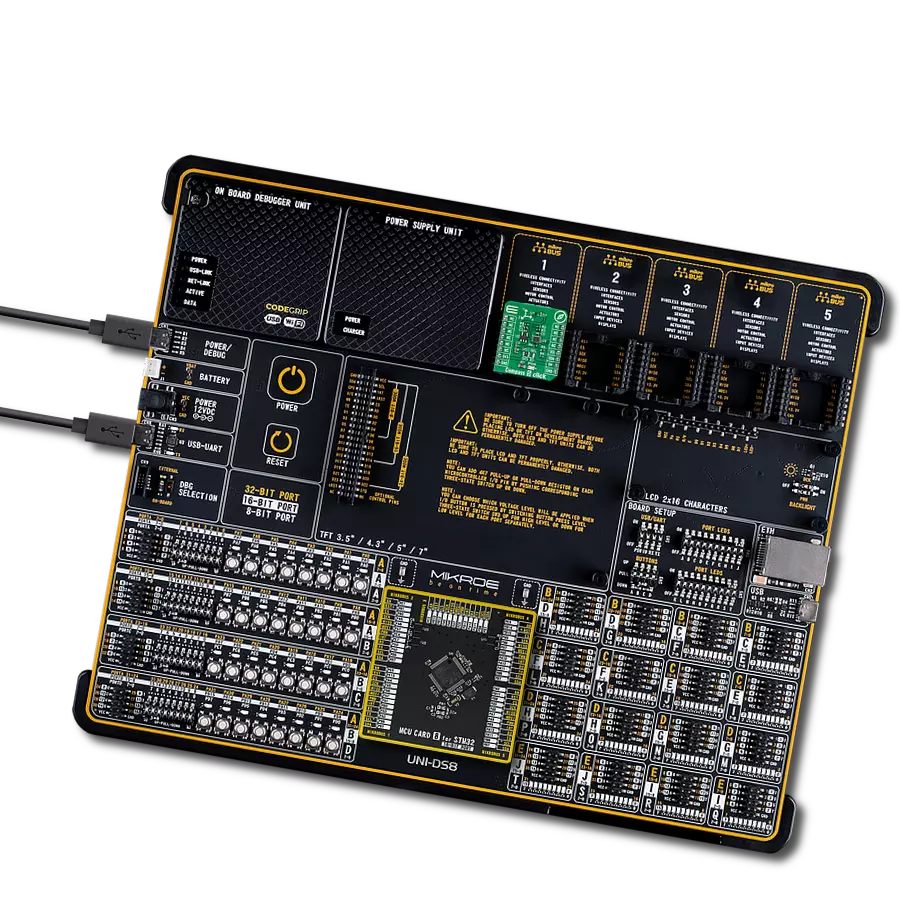
Development board
UNI-DS v8 is a development board specially designed for the needs of rapid development of embedded applications. It supports a wide range of microcontrollers, such as different STM32, Kinetis, TIVA, CEC, MSP, PIC, dsPIC, PIC32, and AVR MCUs regardless of their number of pins, and a broad set of unique functions, such as the first-ever embedded debugger/programmer over WiFi. The development board is well organized and designed so that the end-user has all the necessary elements, such as switches, buttons, indicators, connectors, and others, in one place. Thanks to innovative manufacturing technology, UNI-DS v8 provides a fluid and immersive working experience, allowing access anywhere and under any
circumstances at any time. Each part of the UNI-DS v8 development board contains the components necessary for the most efficient operation of the same board. An advanced integrated CODEGRIP programmer/debugger module offers many valuable programming/debugging options, including support for JTAG, SWD, and SWO Trace (Single Wire Output)), and seamless integration with the Mikroe software environment. Besides, it also includes a clean and regulated power supply module for the development board. It can use a wide range of external power sources, including a battery, an external 12V power supply, and a power source via the USB Type-C (USB-C) connector. Communication options such as USB-UART, USB
HOST/DEVICE, CAN (on the MCU card, if supported), and Ethernet is also included. In addition, it also has the well-established mikroBUS™ standard, a standardized socket for the MCU card (SiBRAIN standard), and two display options for the TFT board line of products and character-based LCD. UNI-DS v8 is an integral part of the Mikroe ecosystem for rapid development. Natively supported by Mikroe software tools, it covers many aspects of prototyping and development thanks to a considerable number of different Click boards™ (over a thousand boards), the number of which is growing every day.

Microcontroller Overview
MCU Card / MCU
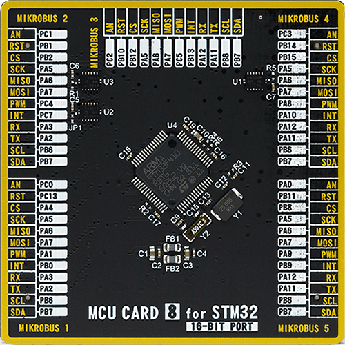
Type
8th Generation
Architecture
ARM Cortex-M4
MCU Memory (KB)
128
Silicon Vendor
STMicroelectronics
Pin count
64
RAM (Bytes)
32768
Used MCU Pins
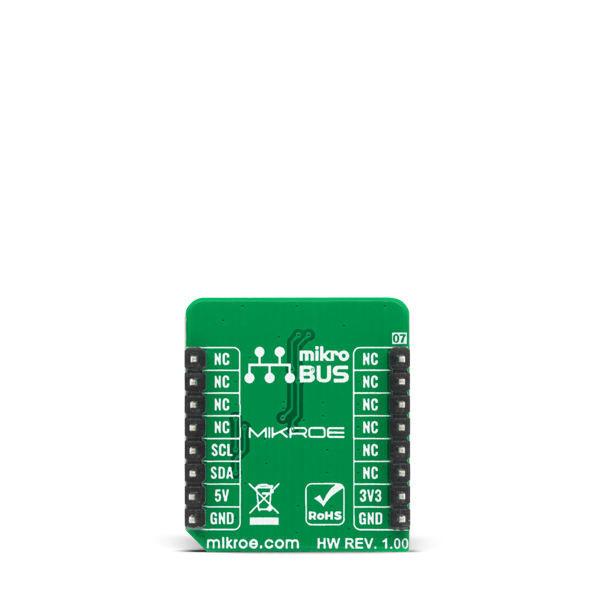
mikroBUS™ mapper
Take a closer look
Click board™ Schematic
Step by step
Project assembly

Start by selecting your development board and Click board™. Begin with the UNI-DS v8 as your development board.


Software Support
Library Description
This library contains API for Compass 5 Click driver.
Key functions:
compass5_write_byte- This function writes a desired number of data bytes starting from the selected register by using I2C serial interfacecompass5_read_byte- This function read 1 bytecompass5_sw_reset- This function for software reset.
Open Source
Code example
The complete application code and a ready-to-use project are available through the NECTO Studio Package Manager for direct installation in the NECTO Studio. The application code can also be found on the MIKROE GitHub account.
/*!
 * @file main.c
 * @brief Compass5 Click example
 *
 * # Description
 * This is an example that demonstrates the use of Compass 5 Click board that reads data
 * from magnetic sensors for X, Y, and Z axes,processes it and displays it via the UART terminal.
 *
 * The demo application is composed of two sections :
 *
 * ## Application Init
 * Initializes I2C and starts to write log, performs power down mode, sets continuous measurement mode; also writes log.
 *
 * ## Application Task
 * When Compass 5 Click is connected via I2C communication, then this example, collects data on the current position of the X,
 * Y and Z axes, processes and displays via the UART terminal. All axis data is printed every 2 seconds.
 *
 * @author Jelena Milosavljevic
 *
 */

#include "board.h"
#include "log.h"
#include "compass5.h"

static compass5_t compass5;
static log_t logger;
uint8_t device_id;
uint8_t company_id;
static char log_txt[ 50 ];

void application_init ( void ) {
    log_cfg_t log_cfg;                /**< Logger config object. */
    compass5_cfg_t compass5_cfg;      /**< Click config object. */

    /**
     * Logger initialization.
     * Default baud rate: 115200
     * Default log level: LOG_LEVEL_DEBUG
     * @note If USB_UART_RX and USB_UART_TX
     * are defined as HAL_PIN_NC, you will
     * need to define them manually for log to work.
     * See @b LOG_MAP_USB_UART macro definition for detailed explanation.
     */
    LOG_MAP_USB_UART( log_cfg );
    log_init( &logger, &log_cfg );
    log_info( &logger, " Application Init " );
    Delay_ms ( 100 );

    // Click initialization.
    compass5_cfg_setup( &compass5_cfg );
    COMPASS5_MAP_MIKROBUS( compass5_cfg, MIKROBUS_1 );
    err_t init_flag = compass5_init( &compass5, &compass5_cfg );
    if ( I2C_MASTER_ERROR == init_flag ) {
        log_error( &logger, " Application Init Error. " );
        log_info( &logger, " Please, run program again... " );

        for ( ; ; );
    }
    compass5_sw_reset( &compass5 );
    Delay_ms ( 500 );

    compass5_get_id( &compass5, &company_id, &device_id );

    if  ( ( company_id == COMPASS5_COMPANI_ID_NUM ) && ( device_id == COMPASS5_DEVICE_ID_NUM ) ) {
        log_printf( &logger, "--------------------\r\n" );
        log_printf( &logger, "  Compass 3 Click   \r\n" );
        log_printf( &logger, "--------------------\r\n" );
    }
    else {
        log_printf( &logger, "   Fatal error!!!   \r\n" );
        for ( ; ; );
    }
    Delay_ms ( 100 );

    log_printf( &logger, "  Power Down Mode  \r\n" );
    log_printf( &logger, "-------------------\r\n" );
    compass5_set_operation_mode( &compass5, COMPASS5_MODE_POWER_DOWN );
    Delay_ms ( 100 );

    log_printf( &logger, "    Continuous     \r\n" );
    log_printf( &logger, " Measurement Mode  \r\n" );
    log_printf( &logger, "-------------------\r\n" );
    compass5_set_operation_mode( &compass5, COMPASS5_MODE_CON_MEASUREMENT_100HZ );
    Delay_ms ( 100 );

    log_printf( &logger, " Start Measurement \r\n" );
    log_printf( &logger, "-------------------\r\n" );
    Delay_ms ( 100 );
    log_info( &logger, " Application Task " );
}

void application_task ( void ) {
    int16_t x_val;
    int16_t y_val;
    int16_t z_val;

    if ( compass5_check_data_ready( &compass5 ) == COMPASS5_DATA_READY ) {
        compass5_measurement_axis( &compass5, &x_val, &y_val, &z_val );
        Delay_ms ( 10 );

        log_printf( &logger, " X-axis: %d mG\r\n", x_val );
        log_printf( &logger, " Y-axis: %d mG\r\n", y_val );
        log_printf( &logger, " Z-axis: %d mG\r\n", z_val );
        log_printf( &logger,  "--------------------\r\n" );
    }
    Delay_ms ( 1000 );
    Delay_ms ( 1000 );
}

int main ( void )
{
    /* Do not remove this line or clock might not be set correctly. */
    #ifdef PREINIT_SUPPORTED
    preinit();
    #endif

    application_init( );

    for ( ; ; )
    {
        application_task( );
    }

    return 0;
}

// ------------------------------------------------------------------------ END
Additional Support
Resources
Category:Magnetic


