Convert digital code into a symphony of analog perfection using DAC80502 and PIC32MZ2048EFM144
Breathe life into digital signals
Published Jul 22, 2025
Click board™
DAC 15 Click
Dev. board
Curiosity PIC32MZ EF 2.0 Development Board
Compiler
NECTO Studio
MCU
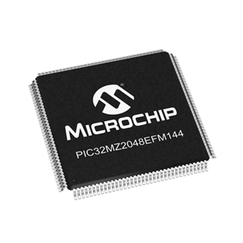
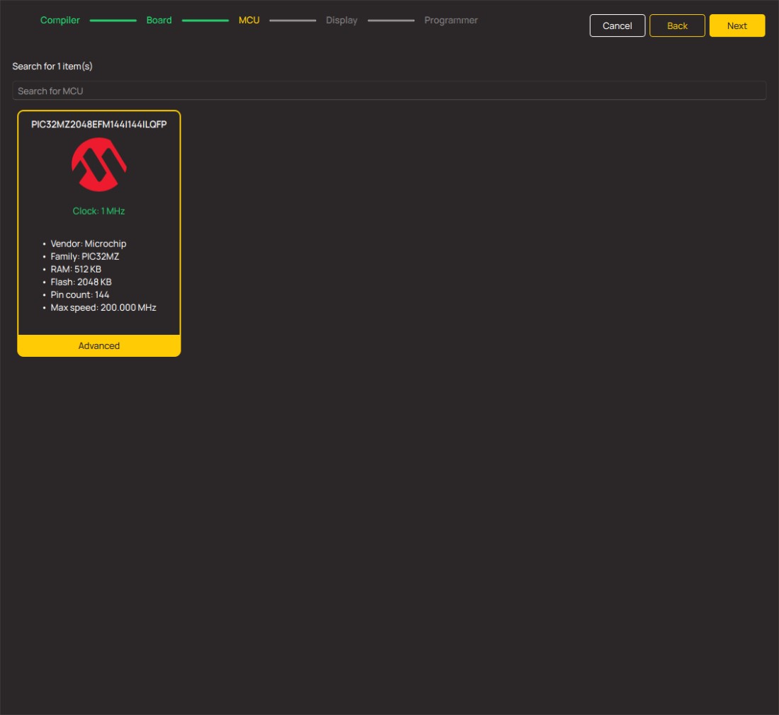
PIC32MZ2048EFM144
Create a universal bridge for converting digital data into rich, analog expressions, catering to diverse needs across industries.
A
A
Hardware Overview
How does it work?
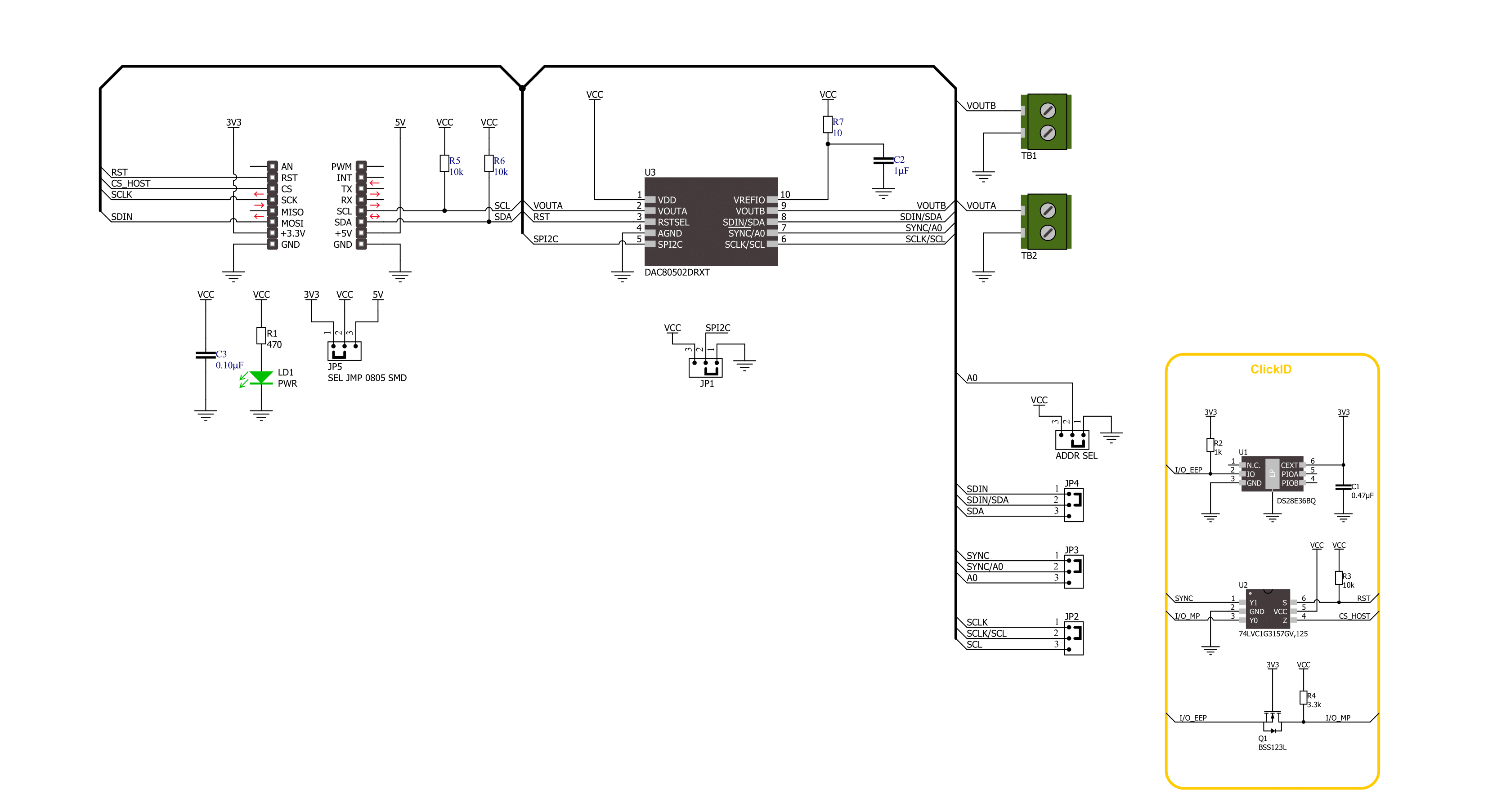
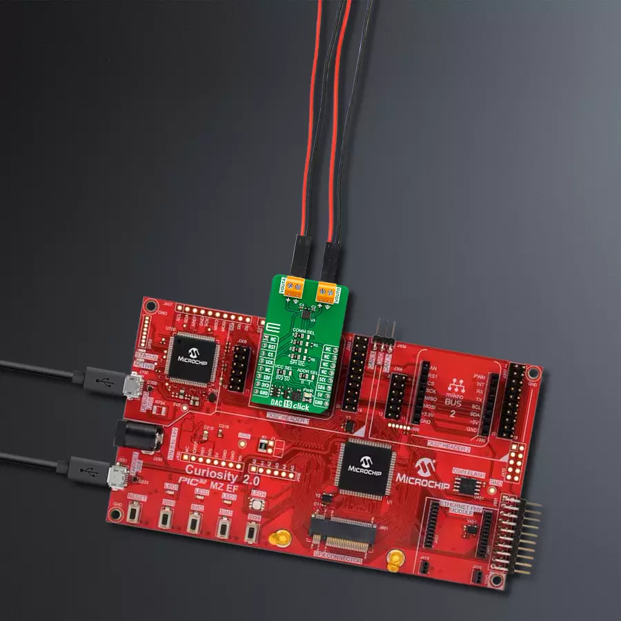
DAC 15 Click is based on the DAC80502, a dual 16-bit 1-LSB INL voltage-output DAC from Texas Instruments. Each device output consists of a rail-to-rail ladder architecture with an output buffer amplifier. The DAC generates rail-to-rail voltages on the output, giving a maximum output range of 0V to a VDD, which depends on a selected voltage on the VCC SEL jumper. The DAC80502 incorporates a power-on-reset circuit that ensures the DAC output powers up at zero scale or midscale based on the RST pin status and remains
at that scale until a valid code is written to the device. DAC 15 Click allows I2C and SPI interfaces to communicate with the host MCU. The I2C interface supports standard, fast, and fast-node plus (1Mbps), whereas while using the last one at 1MHz, the clock update rate is limited to 55.55kSPS. The 3-Wire SPI serial interface operates up to 50kHz and is compatible with SPI, QSPI, and Microwave interface standards. The communication interface can be selected over COMM SEL jumpers. All four jumpers must be set
for the board to work properly (SPI is set by default). If you select the I2C interface, you can also select the I2C address over the ADDR SEL jumper, where 0 is set by default. This Click board™ can operate with either 3.3V or 5V logic voltage levels selected via the VCC SEL jumper. This way, both 3.3V and 5V capable MCUs can use the communication lines properly. Also, this Click board™ comes equipped with a library containing easy-to-use functions and an example code that can be used for further development.

Features overview
Development board
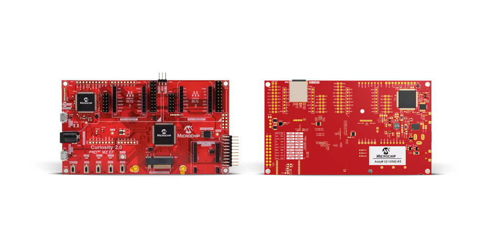
The Curiosity PIC32MZ EF 2.0 Development Board (DM320209) is a fully integrated development platform built around the high-performance PIC32MZ2048EFM144 microcontroller, featuring a 200MHz CPU, 2MB of Flash, and 512KB of SRAM. It comes equipped with an onboard PKoB4 debugger that provides real-time programming and debugging capabilities, along with a Virtual COM port (VCOM) and Data Gateway Interface (DGI), eliminating the need for any external programming hardware. The board is designed for flexibility and expandability, supporting a wide range of
application development needs through its multiple interfaces and expansion options. It includes two mikroBUS™ sockets for integration with MIKROE Click board™ add-ons, two X32 audio interfaces for Bluetooth® and audio functionality, and dedicated interfaces for Ethernet, graphics, and CAN communication. The board also supports Wi-Fi™ connectivity and audio I/O via compatible Microchip daughter boards, and features an Xplained Pro extension interface for additional peripheral expansion. User interaction is enabled through configurable buttons and LEDs, while 8MB of
onboard QSPI memory provides ample space for data storage in demanding applications. Additionally, the Arduino Uno R3 compatible interface allows easy connection with a wide range of Arduino shields. With its rich set of peripherals and robust processing capabilities, the Curiosity PIC32MZ EF 2.0 Development Board is ideally suited for developing complex applications such as Bluetooth® audio systems, IoT devices, robotics platforms, CAN-based networks, and advanced graphical user interfaces.
Microcontroller Overview
MCU Card / MCU
Architecture
PIC32
MCU Memory (KB)
2048
Silicon Vendor
Microchip
Pin count
144
RAM (Bytes)
524288
Used MCU Pins
mikroBUS™ mapper
Take a closer look
Click board™ Schematic
Step by step
Project assembly
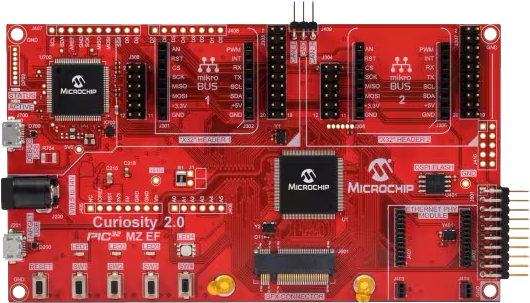
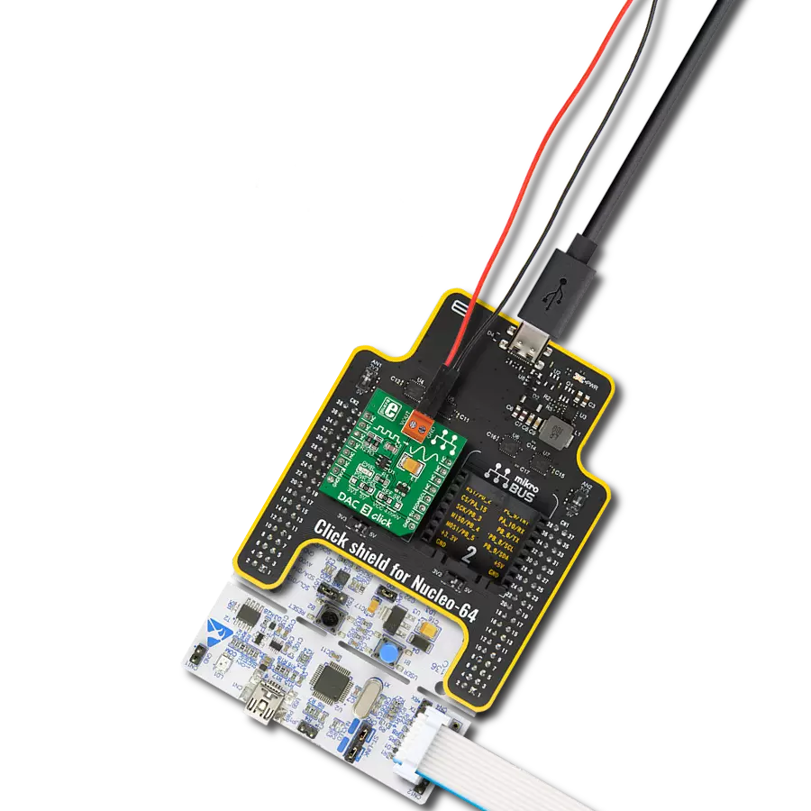
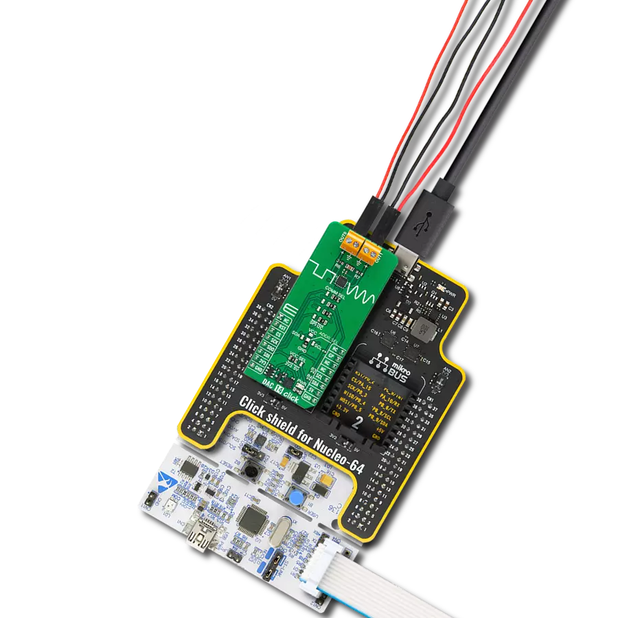
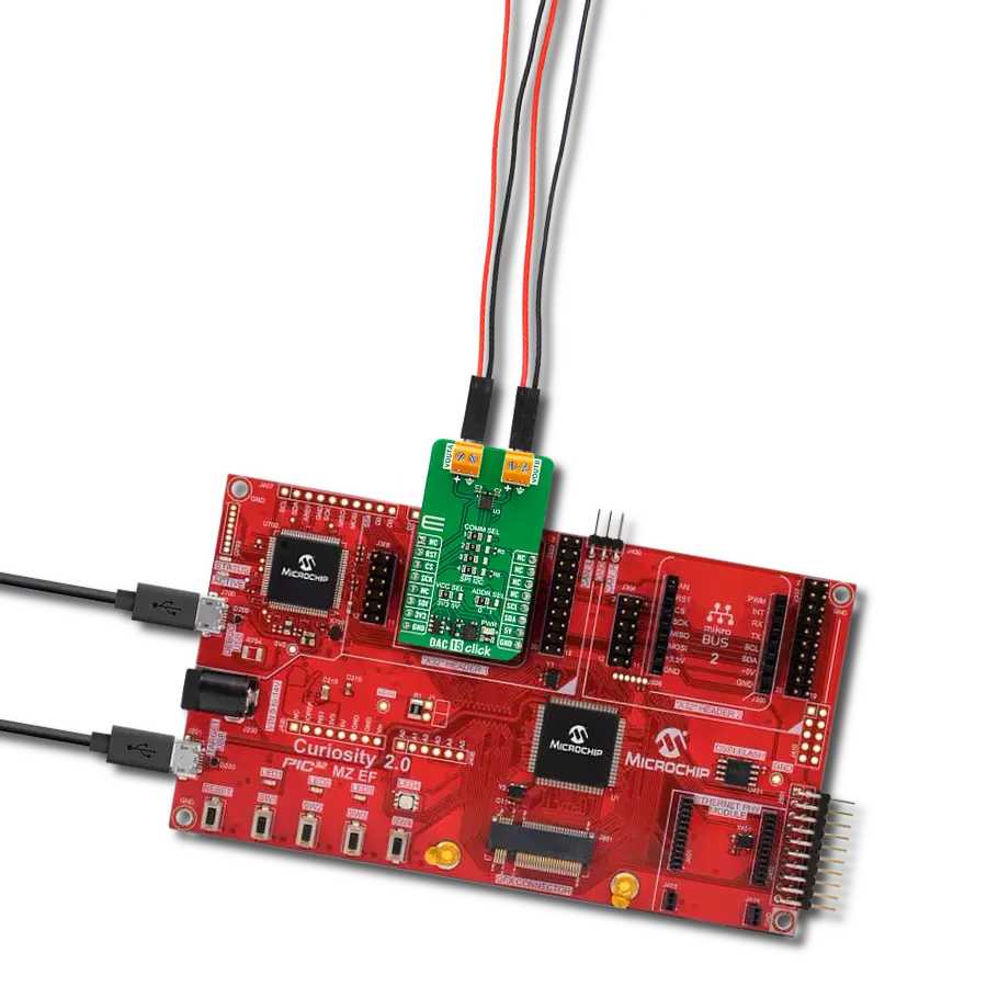
Start by selecting your development board and Click board™. Begin with the Curiosity PIC32MZ EF 2.0 Development Board as your development board.


Software Support
Library Description
This library contains API for DAC 15 Click driver.
Key functions:
dac15_set_dac_data- DAC 15 set DAC data function.dac15_get_dac_data- DAC 15 get DAC data function.
Open Source
Code example
The complete application code and a ready-to-use project are available through the NECTO Studio Package Manager for direct installation in the NECTO Studio. The application code can also be found on the MIKROE GitHub account.
/*!
 * @file main.c
 * @brief DAC 15 Click example
 *
 * # Description
 * This example demonstrates the use of DAC 15 Click board™
 * by changing the output voltage level on the VOUTA and VOUTB.
 *
 * The demo application is composed of two sections :
 *
 * ## Application Init
 * Initialization of I2C or SPI module and log UART.
 * After driver initialization, the app executes a default configuration.
 *
 * ## Application Task
 * The demo application changes the output voltage level on the VOUTA and VOUTB.
 * Results are being sent to the UART Terminal, where you can track their changes.
 *
 * @author Nenad Filipovic
 *
 */

#include "board.h"
#include "log.h"
#include "dac15.h"

static dac15_t dac15;
static log_t logger;

void application_init ( void )
{
    log_cfg_t log_cfg;  /**< Logger config object. */
    dac15_cfg_t dac15_cfg;  /**< Click config object. */

    /**
     * Logger initialization.
     * Default baud rate: 115200
     * Default log level: LOG_LEVEL_DEBUG
     * @note If USB_UART_RX and USB_UART_TX
     * are defined as HAL_PIN_NC, you will
     * need to define them manually for log to work.
     * See @b LOG_MAP_USB_UART macro definition for detailed explanation.
     */
    LOG_MAP_USB_UART( log_cfg );
    log_init( &logger, &log_cfg );
    log_info( &logger, " Application Init " );

    // Click initialization.
    dac15_cfg_setup( &dac15_cfg );
    DAC15_MAP_MIKROBUS( dac15_cfg, MIKROBUS_1 );
    err_t init_flag = dac15_init( &dac15, &dac15_cfg );
    if ( ( I2C_MASTER_ERROR == init_flag ) || ( SPI_MASTER_ERROR == init_flag ) )
    {
        log_error( &logger, " Communication init." );
        for ( ; ; );
    }

    if ( DAC15_ERROR == dac15_default_cfg ( &dac15 ) )
    {
        log_error( &logger, " Default configuration." );
        for ( ; ; );
    }

    log_info( &logger, " Application Task " );
    log_printf( &logger, " -------------------\r\n" );
    Delay_ms ( 100 );
}

void application_task ( void )
{
    static uint16_t dac_data = 0;
    for ( uint16_t n_cnt = 0; n_cnt < 60000; n_cnt += 5000 )
    {
        dac_data = n_cnt;
        if ( DAC15_OK == dac15_set_dac_data( &dac15, DAC15_SET_DAC_A, dac_data ) )
        {
            log_printf( &logger, "VOUTA: %u -> %.2f V\r\n",
                        dac_data,
                        ( float ) dac_data * DAC15_VREF_3V3 / DAC15_MAX_DAC_DATA );
        }

        dac_data = DAC15_DAC_RES_16BIT - n_cnt;
        if ( DAC15_OK == dac15_set_dac_data( &dac15, DAC15_SET_DAC_B, dac_data ) )
        {
            log_printf( &logger, "VOUTB: %u -> %.2f V\r\n",
                        dac_data,
                        ( float ) dac_data * DAC15_VREF_3V3 / DAC15_MAX_DAC_DATA );
        }
        log_printf( &logger, " -------------------\r\n" );
        Delay_ms ( 1000 );
        Delay_ms ( 1000 );
        Delay_ms ( 1000 );
    }
}

int main ( void )
{
    /* Do not remove this line or clock might not be set correctly. */
    #ifdef PREINIT_SUPPORTED
    preinit();
    #endif

    application_init( );

    for ( ; ; )
    {
        application_task( );
    }

    return 0;
}

// ------------------------------------------------------------------------ END