Experience the art of signal convergence with TMUX1208 and STM32F031K6
Where signals converge, choices expand!

Published Oct 01, 2024
Click board™
MUX 3 Click
Dev. board
Nucleo 32 with STM32F031K6 MCU
Compiler
NECTO Studio
MCU
STM32F031K6
Crafted for versatility and precision, our general-purpose CMOS multiplexer empowers you to effortlessly manage and direct various signals, expanding your options for seamless connectivity
A
A
Hardware Overview
How does it work?
MUX 3 Click is based on the TMUX1208, a 5-V Bidirectional 8:1, 1-Channel Multiplexer from Texas Instruments. The TMUX1208 is a general-purpose complementary metal-oxide semiconductor (CMOS) multiplexer (MUX). A wide operating supply of 1.08 V to 5.5 V allows use in various applications, from personal electronics to building automation applications. The device supports bidirectional analog and digital signals on the source (Sx) and drain (D) pins ranging from GND to VDD. All logic inputs have 1.8 V logic-compatible thresholds, ensuring TTL and CMOS logic compatibility when operating in the valid supply voltage range. Fail-Safe Logic circuitry allows voltages on the control pins to be applied before the supply pin, protecting the device from
potential damage. Break-before-make delay is a safety feature that prevents two inputs from connecting when switching devices. The output first breaks from the on-state switch before making the connection with the next on-state switch. The time delay between the break and the make is known as the break-before-make delay. One useful application for the TMUX1208 features is multiplexing various signals into an ADC integrated into an MCU. Utilizing an integrated ADC in the MCU allows a system to minimize cost with a potential tradeoff of system performance when compared to an external ADC. The multiplexer allows for multiple inputs/sensors to be monitored with a single ADC pin of the device, which is critical in systems with limited I/O. Given
all the features the TMUX1208 offers, the MUX 3 Click is best used for Analog and Digital Multiplexing / Demultiplexing, HVAC: Heating, Ventilation, and Air Conditioning, Smoke Detectors, Video Surveillance, Electronic Point of Sale, Battery-Powered Equipment, Appliances, Consumer Audio. This Click board™ can operate with either 3.3V or 5V logic voltage levels selected via the VCC SEL jumper. This way, both 3.3V and 5V capable MCUs can use the communication lines properly. Also, this Click board™ comes equipped with a library containing easy-to-use functions and an example code that can be used, as a reference, for further development.


Features overview
Development board
Nucleo 32 with STM32F031K6 MCU board provides an affordable and flexible platform for experimenting with STM32 microcontrollers in 32-pin packages. Featuring Arduino™ Nano connectivity, it allows easy expansion with specialized shields, while being mbed-enabled for seamless integration with online resources. The
board includes an on-board ST-LINK/V2-1 debugger/programmer, supporting USB reenumeration with three interfaces: Virtual Com port, mass storage, and debug port. It offers a flexible power supply through either USB VBUS or an external source. Additionally, it includes three LEDs (LD1 for USB communication, LD2 for power,
and LD3 as a user LED) and a reset push button. The STM32 Nucleo-32 board is supported by various Integrated Development Environments (IDEs) such as IAR™, Keil®, and GCC-based IDEs like AC6 SW4STM32, making it a versatile tool for developers.

Microcontroller Overview
MCU Card / MCU

Architecture
ARM Cortex-M0
MCU Memory (KB)
32
Silicon Vendor
STMicroelectronics
Pin count
32
RAM (Bytes)
4096
You complete me!
Accessories
Click Shield for Nucleo-32 is the perfect way to expand your development board's functionalities with STM32 Nucleo-32 pinout. The Click Shield for Nucleo-32 provides two mikroBUS™ sockets to add any functionality from our ever-growing range of Click boards™. We are fully stocked with everything, from sensors and WiFi transceivers to motor control and audio amplifiers. The Click Shield for Nucleo-32 is compatible with the STM32 Nucleo-32 board, providing an affordable and flexible way for users to try out new ideas and quickly create prototypes with any STM32 microcontrollers, choosing from the various combinations of performance, power consumption, and features. The STM32 Nucleo-32 boards do not require any separate probe as they integrate the ST-LINK/V2-1 debugger/programmer and come with the STM32 comprehensive software HAL library and various packaged software examples. This development platform provides users with an effortless and common way to combine the STM32 Nucleo-32 footprint compatible board with their favorite Click boards™ in their upcoming projects.

Used MCU Pins
mikroBUS™ mapper
Take a closer look
Click board™ Schematic

Step by step
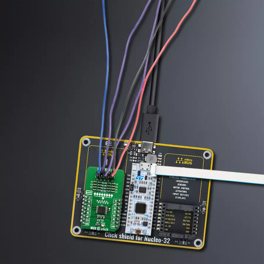
Project assembly

Start by selecting your development board and Click board™. Begin with the Nucleo 32 with STM32F031K6 MCU as your development board.


Software Support
Library Description
This library contains API for MUX 3 Click driver.
Key functions:
mux3_set_channel- Set active MUX channel function
Open Source
Code example
The complete application code and a ready-to-use project are available through the NECTO Studio Package Manager for direct installation in the NECTO Studio. The application code can also be found on the MIKROE GitHub account.
/*!
 * \file
 * \brief MUX 3 Click example
 *
 * # Description
 * This application sets multiplexing one input channel to eight single-ended output channels.
 *
 * The demo application is composed of two sections :
 *
 * ## Application Init
 * Initialization driver enable's - GPIO, also write log.
 *
 * ## Application Task
 * This is an example which demonstrates the use of MUX 3 Click board.
 * Sets the current active and changes the channel every 1 sec.
 * Results are being sent to the Usart Terminal where you can track their changes.
 * All data logs write on Usart Terminal changes for every 1 sec.
 *
 * \author MikroE Team
 *
 */
// ------------------------------------------------------------------- INCLUDES

#include "board.h"
#include "log.h"
#include "mux3.h"

// ------------------------------------------------------------------ VARIABLES

static mux3_t mux3;
static log_t logger;

// ------------------------------------------------------ APPLICATION FUNCTIONS

void application_init ( void )
{
    log_cfg_t log_cfg;
    mux3_cfg_t cfg;

    /**
     * Logger initialization.
     * Default baud rate: 115200
     * Default log level: LOG_LEVEL_DEBUG
     * @note If USB_UART_RX and USB_UART_TX
     * are defined as HAL_PIN_NC, you will
     * need to define them manually for log to work.
     * See @b LOG_MAP_USB_UART macro definition for detailed explanation.
     */
    LOG_MAP_USB_UART( log_cfg );
    log_init( &logger, &log_cfg );
    log_info(&logger, "---- Application Init ----");

    //  Click initialization.

    mux3_cfg_setup( &cfg );
    MUX3_MAP_MIKROBUS( cfg, MIKROBUS_1 );
    mux3_init( &mux3, &cfg );
}

void application_task ( void )
{
    mux3_set_channel( &mux3, MUX3_ENABLE_CHANNEL_S1 );
    log_printf( &logger, "Active channel: S1\r\n" );
    Delay_1sec( );

    mux3_set_channel( &mux3, MUX3_ENABLE_CHANNEL_S2 );
    log_printf( &logger, "Active channel: S2\r\n" );
    Delay_1sec( );

    mux3_set_channel( &mux3, MUX3_ENABLE_CHANNEL_S3 );
    log_printf( &logger, "Active channel: S3\r\n" );
    Delay_1sec( );

    mux3_set_channel( &mux3, MUX3_ENABLE_CHANNEL_S4 );
    log_printf( &logger, "Active channel: S4\r\n" );
    Delay_1sec( );

    mux3_set_channel( &mux3, MUX3_ENABLE_CHANNEL_S5 );
    log_printf( &logger, "Active channel: S5\r\n" );
    Delay_1sec( );

    mux3_set_channel( &mux3, MUX3_ENABLE_CHANNEL_S6 );
    log_printf( &logger, "Active channel: S6\r\n" );
    Delay_1sec( );

    mux3_set_channel( &mux3, MUX3_ENABLE_CHANNEL_S7 );
    log_printf( &logger, "Active channel: S7\r\n" );
    Delay_1sec( );

    mux3_set_channel( &mux3, MUX3_ENABLE_CHANNEL_S8 );
    log_printf( &logger, "Active channel: S8\r\n" );
    Delay_1sec( );

    mux3_set_channel( &mux3, MUX3_DISABLE_ALL_CHANNELS );
    log_printf( &logger, "Active channel: none\r\n" );
    log_printf( &logger, "-------------------\r\n" );
    Delay_1sec( );
}

int main ( void )
{
    /* Do not remove this line or clock might not be set correctly. */
    #ifdef PREINIT_SUPPORTED
    preinit();
    #endif

    application_init( );

    for ( ; ; )
    {
        application_task( );
    }

    return 0;
}

// ------------------------------------------------------------------------ END
Additional Support
Resources
Category:DAC


