Unlock the secrets of time with DS1343 combined with TM4C129ENCPDT
RTC: Time's trusted guardians in the digital age
Published Oct 21, 2023
Click board™
RTC 12 Click
Dev. board
Fusion for Tiva v8
Compiler
NECTO Studio
MCU
TM4C129ENCPDT
Optimize your engineering projects with efficient real-time clock, delivering reliable and accurate timekeeping for critical operations
A
A
Hardware Overview
How does it work?
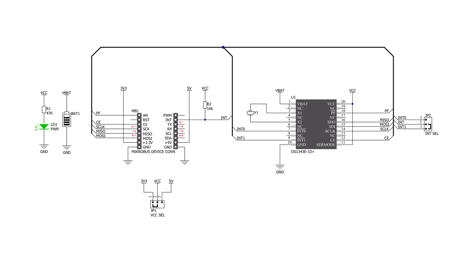
RTC 12 Click is based on the DS1343, a low-current RTC that consumes an extremely low timekeeping current, permitting longer life from a backup supply source from Analog Devices. The devices provide a full binary-coded decimal clock calendar accessed by a simple serial interface. The clock/calendar provides information on seconds, minutes, hours, days, dates, months, and years. The month's end date is automatically adjusted for months with fewer than 31 days, including corrections for the leap year through 2099. The clock operates in either a 24-hour or 12-hour format with an AM/PM indicator. As performed on this Click board™, the most common configuration is a battery-backed-up RTC, which maintains time and may hold data in 96 bytes of NV RAM provided for data storage. In addition to
the DS1343, the RTC 12 Click is equipped with a button cell battery holder compatible with the 3000TR battery holder, suitable for 12mm Coin Cell batteries. Furthermore, it has a built-in temperature-compensated power-sense circuit that detects power failures and automatically switches to the backup supply, thus allowing for uninterrupted operation. The DS1343 communicates with MCU using the standard SPI serial interface that supports modes 1 and 3 with a maximum frequency of 4 MHz. It also provides two programmable time-of-day alarms. Each alarm can generate an interrupt on a programmable combination of seconds, minutes, hours, and days, available on the INT pin of the mikroBUS™ socket. The interrupt selection can be made by positioning the SMD jumper labeled INT SEL to an
appropriate position. Both interrupt outputs operate when the device is powered by mikroBUS™ power rails or backup supply voltage. In addition to the features mentioned above, the user can use another indicator routed to the AN pin of the mikroBUS™ socket labeled as PF to indicate a loss of a primary power supply, VCC, from mikroBUS™ power rails. This Click board™ can operate with either 3.3V or 5V logic voltage levels selected via the VCC SEL jumper. This way, both 3.3V and 5V capable MCUs can use the communication lines properly. Also, this Click board™ comes equipped with a library containing easy-to-use functions and an example code that can be used as a reference for further development.


Features overview
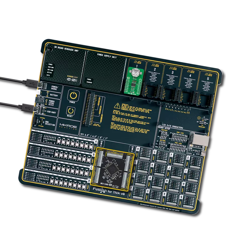
Development board
Fusion for TIVA v8 is a development board specially designed for the needs of rapid development of embedded applications. It supports a wide range of microcontrollers, such as different 32-bit ARM® Cortex®-M based MCUs from Texas Instruments, regardless of their number of pins, and a broad set of unique functions, such as the first-ever embedded debugger/programmer over a WiFi network. The development board is well organized and designed so that the end-user has all the necessary elements, such as switches, buttons, indicators, connectors, and others, in one place. Thanks to innovative manufacturing technology, Fusion for TIVA v8 provides a fluid and immersive working experience, allowing access
anywhere and under any circumstances at any time. Each part of the Fusion for TIVA v8 development board contains the components necessary for the most efficient operation of the same board. An advanced integrated CODEGRIP programmer/debugger module offers many valuable programming/debugging options, including support for JTAG, SWD, and SWO Trace (Single Wire Output)), and seamless integration with the Mikroe software environment. Besides, it also includes a clean and regulated power supply module for the development board. It can use a wide range of external power sources, including a battery, an external 12V power supply, and a power source via the USB Type-C (USB-C) connector.
Communication options such as USB-UART, USB HOST/DEVICE, CAN (on the MCU card, if supported), and Ethernet is also included. In addition, it also has the well-established mikroBUS™ standard, a standardized socket for the MCU card (SiBRAIN standard), and two display options for the TFT board line of products and character-based LCD. Fusion for TIVA v8 is an integral part of the Mikroe ecosystem for rapid development. Natively supported by Mikroe software tools, it covers many aspects of prototyping and development thanks to a considerable number of different Click boards™ (over a thousand boards), the number of which is growing every day.

Microcontroller Overview
MCU Card / MCU

Type
8th Generation
Architecture
ARM Cortex-M4
MCU Memory (KB)
1024
Silicon Vendor
Texas Instruments
Pin count
128
RAM (Bytes)
262144
Used MCU Pins
mikroBUS™ mapper
Take a closer look
Click board™ Schematic
Step by step
Project assembly

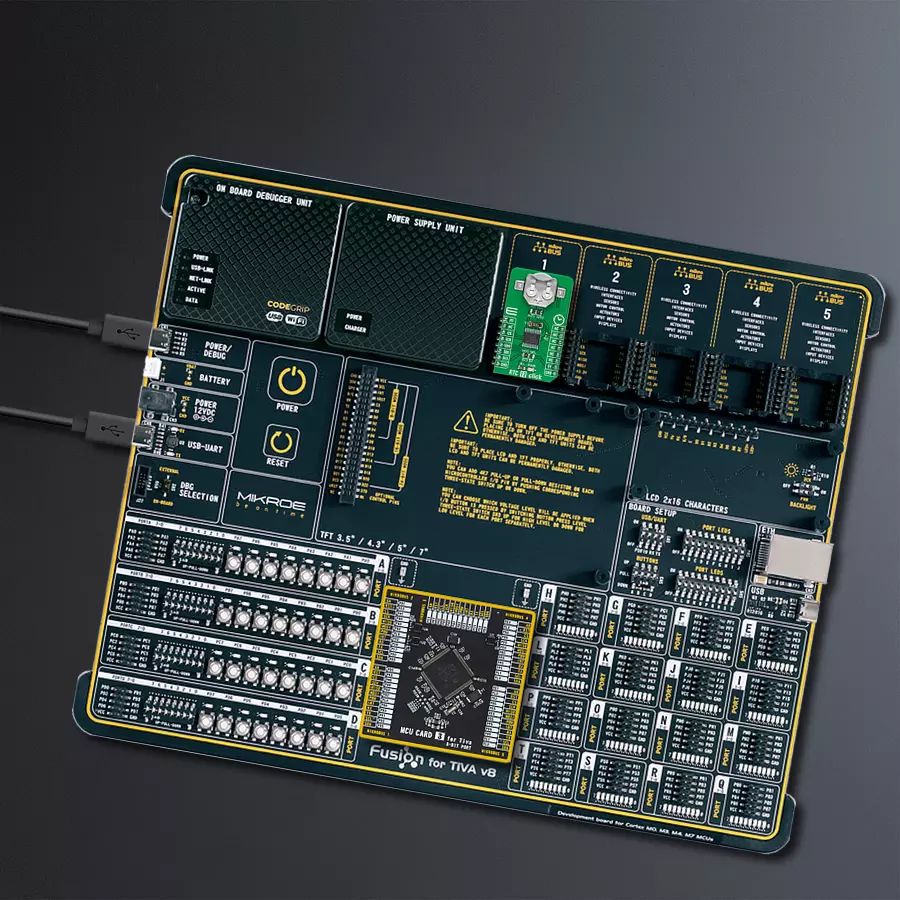
Start by selecting your development board and Click board™. Begin with the Fusion for Tiva v8 as your development board.


Software Support
Library Description
This library contains API for RTC 12 Click driver.
Key functions:
rtc12_set_time- RTC 12 set time functionrtc12_get_time- RTC 12 get time functionrtc12_get_date- RTC 12 get date function
Open Source
Code example
The complete application code and a ready-to-use project are available through the NECTO Studio Package Manager for direct installation in the NECTO Studio. The application code can also be found on the MIKROE GitHub account.
/*!
 * @file main.c
 * @brief Rtc12 Click example
 *
 * # Description
 * This is an example that demonstrates the use of the RTC 12 Click board™.
 *
 *
 * The demo application is composed of two sections :
 *
 * ## Application Init
 * Initialization of SPI module, log UART and additional pins.
 * After driver initialization and default settings,
 * the app set the time to 23:59:50 and set the date to 27.05.'21.
 *
 * ## Application Task
 * This is an example that shows the use of a RTC 12 Click board™.
 * In this example, we read and display the current time and date,
 * which we also previously set.
 * Results are being sent to the Usart Terminal where you can track their changes.
 * All data logs write on USB changes every 1 sec.
 *
 *
 * @author Nenad Filipovic
 *
 */

#include "board.h"
#include "log.h"
#include "rtc12.h"

static rtc12_t rtc12;
static log_t logger;

static uint8_t new_sec = 255;
static rtc12_time_t time;
static rtc12_date_t date;


void application_init ( void ) {
    log_cfg_t log_cfg;      /**< Logger config object. */
    rtc12_cfg_t rtc12_cfg;   /**< Click config object. */

    /**
     * Logger initialization.
     * Default baud rate: 115200
     * Default log level: LOG_LEVEL_DEBUG
     * @note If USB_UART_RX and USB_UART_TX
     * are defined as HAL_PIN_NC, you will
     * need to define them manually for log to work.
     * See @b LOG_MAP_USB_UART macro definition for detailed explanation.
     */
    LOG_MAP_USB_UART( log_cfg );
    log_init( &logger, &log_cfg );
    log_info( &logger, " Application Init " );

    // Click initialization.

    rtc12_cfg_setup( &rtc12_cfg );
    RTC12_MAP_MIKROBUS( rtc12_cfg, MIKROBUS_1 );
    err_t init_flag  = rtc12_init( &rtc12, &rtc12_cfg );
    if ( init_flag == SPI_MASTER_ERROR ) {
        log_error( &logger, " Application Init Error. " );
        log_info( &logger, " Please, run program again... " );

        for ( ; ; );
    }

    rtc12_default_cfg ( &rtc12 );
    log_info( &logger, " Application Task " );
    Delay_ms ( 100 );

    date.day_of_week = 4;
    date.day = 27;
    date.month = 5;
    date.year = 21;
    rtc12_set_date( &rtc12, date );
    Delay_ms ( 100 );

    time.hours = 23;
    time.min = 59;
    time.sec = 50;
    rtc12_set_time( &rtc12, time );
    Delay_ms ( 100 );
}

void application_task ( void ) {
    rtc12_get_time( &rtc12, &time );
    Delay_ms ( 1 );
    rtc12_get_date( &rtc12, &date );
    Delay_ms ( 1 );

    if ( time.sec != new_sec ) {
        log_printf( &logger, "  Date      : %.2d-%.2d-%.2d\r\n", ( uint16_t ) date.day, ( uint16_t ) date.month, ( uint16_t ) date.year );
        log_printf( &logger, "  Time      : %.2d:%.2d:%.2d\r\n", ( uint16_t ) time.hours, ( uint16_t ) time.min, ( uint16_t ) time.sec );
        log_printf( &logger, "- - - - - - - - - - - -\r\n" );
        new_sec = time.sec;
        Delay_ms ( 1 );
     }
}

int main ( void )
{
    /* Do not remove this line or clock might not be set correctly. */
    #ifdef PREINIT_SUPPORTED
    preinit();
    #endif

    application_init( );

    for ( ; ; )
    {
        application_task( );
    }

    return 0;
}

// ------------------------------------------------------------------------ END


