Track the climate with ease using HTU21D and TM4C129ENCPDT
From scorching heat to refreshing breezes

Published Jun 21, 2023
Click board™
HTU21D Click
Dev. board
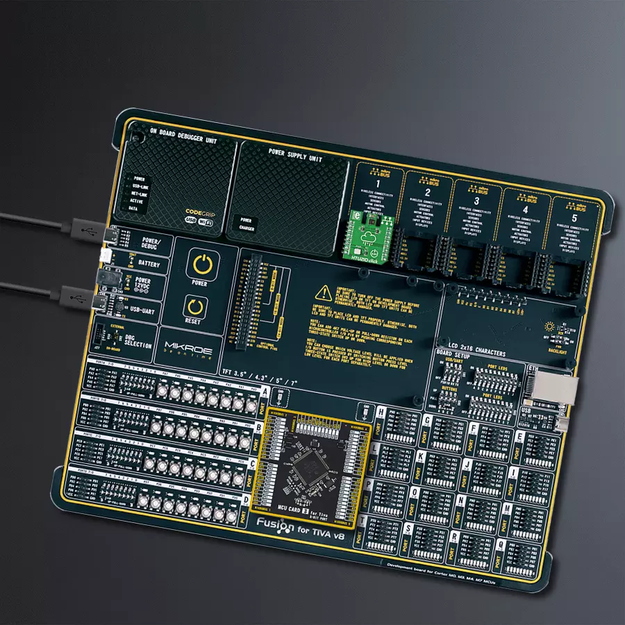
Fusion for Tiva v8
Compiler
NECTO Studio
MCU
TM4C129ENCPDT
Ensure optimal conditions for enhanced productivity and well-being in any indoor environment
A
A
Hardware Overview
How does it work?
HTU21D Click is based on the HTU21D, an easy-to-use, highly accurate digital humidity sensor with temperature output from TE Connectivity. The HTU21D can read humidity over the full range of 0 to 100% RH with a typical accuracy of ±2% over the range of 5% to 95% RH, while its maximum temperature range is from -40 to 125°C. It has a typical accuracy of ±0.3°C over 0 to 70°C. The HTU21D makes a perfect choice for environmental sensing and data logging for weather stations or humidity control systems. It should be noted that
this sensor isn’t recommended for harsh environments where it could come in contact with water (such as rain). The HTU21D has a resolution of 0.7% RH and 0.040°C with conversion times of 2ms and 11ms, respectively. For more demanding requirements, the HTU21D allows users to increase the resolution at the expense of increased conversion time. For example, in full resolution mode, the HTU21D can provide 0.04% RH with a conversion time of 14ms and 0.01°C with a conversion time of 44ms. The HTU21D
communicates with MCU using the standard I2C 2-Wire interface with a maximum frequency of 400kHz and a fixed I2C address set to 0x40. This Click board™ can be operated only with a 3.3V logic voltage level. The board must perform appropriate logic voltage level conversion before using MCUs with different logic levels. However, the Click board™ comes equipped with a library containing functions and an example code that can be used, as a reference, for further development.

Features overview
Development board
Fusion for TIVA v8 is a development board specially designed for the needs of rapid development of embedded applications. It supports a wide range of microcontrollers, such as different 32-bit ARM® Cortex®-M based MCUs from Texas Instruments, regardless of their number of pins, and a broad set of unique functions, such as the first-ever embedded debugger/programmer over a WiFi network. The development board is well organized and designed so that the end-user has all the necessary elements, such as switches, buttons, indicators, connectors, and others, in one place. Thanks to innovative manufacturing technology, Fusion for TIVA v8 provides a fluid and immersive working experience, allowing access
anywhere and under any circumstances at any time. Each part of the Fusion for TIVA v8 development board contains the components necessary for the most efficient operation of the same board. An advanced integrated CODEGRIP programmer/debugger module offers many valuable programming/debugging options, including support for JTAG, SWD, and SWO Trace (Single Wire Output)), and seamless integration with the Mikroe software environment. Besides, it also includes a clean and regulated power supply module for the development board. It can use a wide range of external power sources, including a battery, an external 12V power supply, and a power source via the USB Type-C (USB-C) connector.
Communication options such as USB-UART, USB HOST/DEVICE, CAN (on the MCU card, if supported), and Ethernet is also included. In addition, it also has the well-established mikroBUS™ standard, a standardized socket for the MCU card (SiBRAIN standard), and two display options for the TFT board line of products and character-based LCD. Fusion for TIVA v8 is an integral part of the Mikroe ecosystem for rapid development. Natively supported by Mikroe software tools, it covers many aspects of prototyping and development thanks to a considerable number of different Click boards™ (over a thousand boards), the number of which is growing every day.

Microcontroller Overview
MCU Card / MCU

Type
8th Generation
Architecture
ARM Cortex-M4
MCU Memory (KB)
1024
Silicon Vendor
Texas Instruments
Pin count
128
RAM (Bytes)
262144
Used MCU Pins
mikroBUS™ mapper
Take a closer look
Click board™ Schematic

Step by step
Project assembly

Start by selecting your development board and Click board™. Begin with the Fusion for Tiva v8 as your development board.


Track your results in real time
Application Output
1. Application Output - In Debug mode, the 'Application Output' window enables real-time data monitoring, offering direct insight into execution results. Ensure proper data display by configuring the environment correctly using the provided tutorial.

2. UART Terminal - Use the UART Terminal to monitor data transmission via a USB to UART converter, allowing direct communication between the Click board™ and your development system. Configure the baud rate and other serial settings according to your project's requirements to ensure proper functionality. For step-by-step setup instructions, refer to the provided tutorial.

3. Plot Output - The Plot feature offers a powerful way to visualize real-time sensor data, enabling trend analysis, debugging, and comparison of multiple data points. To set it up correctly, follow the provided tutorial, which includes a step-by-step example of using the Plot feature to display Click board™ readings. To use the Plot feature in your code, use the function: plot(*insert_graph_name*, variable_name);. This is a general format, and it is up to the user to replace 'insert_graph_name' with the actual graph name and 'variable_name' with the parameter to be displayed.

Software Support
Library Description
This library contains API for HTU21D Click driver.
Key functions:
htu21d_cfg_setup- This function initializes click configuration structure to init statehtu21d_init- This function initializes all necessary pins and peripherals used for this clickhtu21d_generic_write- This function writes data to the desired registerhtu21d_generic_read- This function reads data from the desired registerhtu21d_read_data- Function read 24-bit data from register address of the HTU21Dosd_enable_video_buffer- This function enables video bufferosd_clear_display_memory- This function clears display memoryosd_insert_custom_char- This function writes custom characterosd_enable_video_buffer- This function enables video buffer
Open Source
Code example
The complete application code and a ready-to-use project are available through the NECTO Studio Package Manager for direct installation in the NECTO Studio. The application code can also be found on the MIKROE GitHub account.
/*!
 * \file
 * \brief Htu21d Click example
 *
 * # Description
 * The application is composed of two sections.
 *
 * ## Application Init
 * Initialization driver enable's - I2C, soft reset switch OFF
 * and ON the HTU21D sensor,hold ( required )
 * after reset 100 [ ms ] and start write log.
 *
 * ## Application Task
 * This is a example which demonstrates the use of
 * HTU21D Click board.Measured temperature and humidity
 * data from the HDC1000 sensor.Convert temperature data
 * to degrees Celsius and humidity data to percentarg.
 * Results are being sent to the Usart Terminal
 * where you can track their changes.
 * All data logs on usb uart for aproximetly every 3 sec.
 *
 *
 * \author MikroE Team
 *
 */
// ------------------------------------------------------------------- INCLUDES

#include "board.h"
#include "log.h"
#include "htu21d.h"

// ------------------------------------------------------------------ VARIABLES

static htu21d_t htu21d;
static log_t logger;
static float temperature;
static float humidity;

// ------------------------------------------------------- ADDITIONAL FUNCTIONS


// ------------------------------------------------------ APPLICATION FUNCTIONS

void application_init ( void )
{
    log_cfg_t log_cfg;
    htu21d_cfg_t cfg;

    /**
     * Logger initialization.
     * Default baud rate: 115200
     * Default log level: LOG_LEVEL_DEBUG
     * @note If USB_UART_RX and USB_UART_TX
     * are defined as HAL_PIN_NC, you will
     * need to define them manually for log to work.
     * See @b LOG_MAP_USB_UART macro definition for detailed explanation.
     */
    LOG_MAP_USB_UART( log_cfg );
    log_init( &logger, &log_cfg );
    log_info( &logger, "---- Application Init ----" );

    //  Click initialization.

    htu21d_cfg_setup( &cfg );
    HTU21D_MAP_MIKROBUS( cfg, MIKROBUS_1 );
    htu21d_init( &htu21d, &cfg );

    htu21d_send_cmd ( &htu21d, HTU21D_SOFT_RESET );
    Delay_ms ( 500 );

    log_printf( &logger, "-----------------------\r\n" );
    log_printf( &logger, "         HTU21D\r\n" );
    log_printf( &logger, "-----------------------\r\n" );
}

void application_task ( void )
{
    //  Task implementation.
    temperature = htu21d_get_temperature( &htu21d );
    log_printf( &logger, " Temperature : %.2f degC\r\n", temperature );

    humidity = htu21d_get_humidity( &htu21d );
    log_printf( &logger, " Humidity    : %.2f %%\r\n", humidity );
    log_printf( &logger, "-----------------------\r\n" );

    Delay_ms ( 1000 );
    Delay_ms ( 1000 );
    Delay_ms ( 1000 );
}

int main ( void )
{
    /* Do not remove this line or clock might not be set correctly. */
    #ifdef PREINIT_SUPPORTED
    preinit();
    #endif

    application_init( );

    for ( ; ; )
    {
        application_task( );
    }

    return 0;
}


// ------------------------------------------------------------------------ END
Additional Support
Resources
Category:Temperature & humidity


