Provide accurate location data based on satellite signals even in challenging urban areas with MAX-f10S and PIC18F87J11
L1/L5 dual-band professional-grade GNSS receiver
Published Oct 21, 2024
Click board™
GNSS MAX 2 Click
Dev. board
EasyPIC PRO v8
Compiler
NECTO Studio
MCU
PIC18F87J11
Support applications that rely on accurate location data, such as navigation, mapping, and augmented reality
A
A
Hardware Overview
How does it work?
GNSS MAX 2 Click is based on the MAX-F10S, a professional-grade L1/L5 dual-band GNSS receiver from u-blox, designed for achieving meter-level accuracy even in challenging urban environments. This board is built on the u-blox F10 GNSS technology, leveraging both L1 and L5 GNSS bands for enhanced precision. The dual-band capability allows the MAX-F10S to mitigate multipath effects, using signals from both L1 and L5 bands to deliver significantly better positional accuracy than single-band receivers. This Click board™ is ideal for various applications requiring reliable and accurate positioning in urban settings, offering significant benefits for vehicle tracking, fleet management, micromobility solutions, and more, even when used with small antennas. As a concurrent GNSS receiver, the MAX-F10S can track multiple GNSS constellations simultaneously, including GPS, Galileo, and BeiDou systems with SBAS enabled, ensuring robust and reliable performance in complex urban areas. Its RF front-end architecture is designed to receive dual-
frequency signals concurrently, providing high sensitivity and improved accuracy. To further enhance its reliability, the module includes two internal SAW filters and a low-noise amplifier (LNA), protecting the receiver from RF interference caused by nearby cellular modems. Its efficient power management system also allows the receiver to use only a subset of GNSS constellations, reducing power consumption while maintaining high accuracy. The GNSS MAX 2 Click communicates with the host MCU through a UART interface using the standard UART RX and TX pins. The default communication speed is set at 9600bps, ensuring efficient data exchange. It also provides an I2C interface for communication with a host MCU in the I2C Fast mode. Still, it must be noted that the I2C interface can only be operated in the peripheral mode. Besides interface pins, this Click board™ also incorporates a reset pin (RST) for direct module resetting and an external interrupt signal (EXI) that can be programmed for various functions, such as waking up the module.
Furthermore, GNSS 17 Click includes a red PPS LED indicator, which emits a synchronized pulse signal from the MAX-F10S once per second. The PPS function is enabled by default, and the module will output the PPS signal once a 3D fix is achieved. This Click board™ also features the SMA antenna connector with an impedance of 50Ω, compatible with various antennas available from MIKROE, like the Active GPS Antenna, to enhance its connectivity. Also, in the case of the primary supply failure, the module can use a backup supply voltage from a connected battery if you need the Click board™ to be a standalone device. This Click board™ can be operated only with a 3.3V logic voltage level. The board must perform appropriate logic voltage level conversion before using MCUs with different logic levels. Also, it comes equipped with a library containing functions and an example code that can be used as a reference for further development.

Features overview
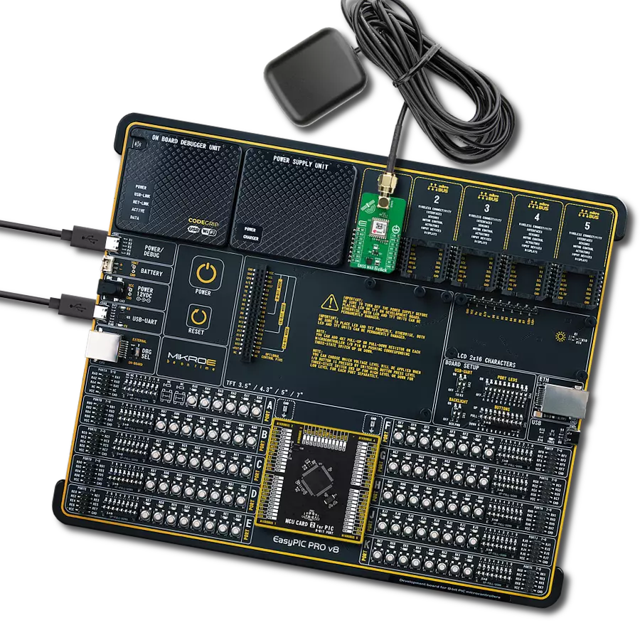
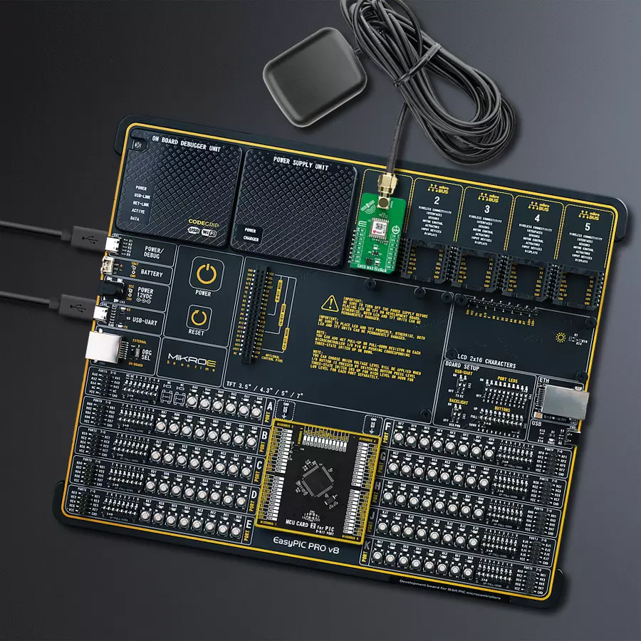
Development board
EasyPIC PRO v8 is a development board specially designed for the needs of rapid development of embedded applications. It supports many high pin count 8-bit PIC microcontrollers from Microchip, regardless of their number of pins, and a broad set of unique functions, such as the first-ever embedded debugger/programmer over WiFi. The development board is well organized and designed so that the end-user has all the necessary elements, such as switches, buttons, indicators, connectors, and others, in one place. Thanks to innovative manufacturing technology, EasyPIC PRO v8 provides a fluid and immersive working experience, allowing access anywhere and under
any circumstances at any time. Each part of the EasyPIC PRO v8 development board contains the components necessary for the most efficient operation of the same board. In addition to the advanced integrated CODEGRIP programmer/debugger module, which offers many valuable programming/debugging options and seamless integration with the Mikroe software environment, the board also includes a clean and regulated power supply module for the development board. It can use a wide range of external power sources, including a battery, an external 12V power supply, and a power source via the USB Type-C (USB-C) connector.
Communication options such as USB-UART, USB DEVICE, and Ethernet are also included, including the well-established mikroBUS™ standard, a standardized socket for the MCU card (SiBRAIN standard), and two display options (graphical and character-based LCD). EasyPIC PRO v8 is an integral part of the Mikroe ecosystem for rapid development. Natively supported by Mikroe software tools, it covers many aspects of prototyping and development thanks to a considerable number of different Click boards™ (over a thousand boards), the number of which is growing every day.

Microcontroller Overview
MCU Card / MCU
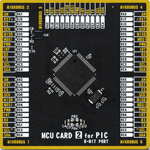
Type
8th Generation
Architecture
PIC
MCU Memory (KB)
128
Silicon Vendor
Microchip
Pin count
80
RAM (Bytes)
3904
You complete me!
Accessories
Active GPS antenna is designed to enhance the performance of your GPS and GNSS Click boards™. This external antenna boasts a robust construction, making it ideal for various weather conditions. With a frequency range of 1575.42MHz and a 50Ohm impedance, it ensures reliable signal reception. The antenna delivers a gain of greater than -4dBic within a wide angular range, securing over 75% coverage. The bandwidth of +/- 5MHz further guarantees precise data acquisition. Featuring a Right-Hand Circular Polarization (RHCP), this antenna offers stable signal reception. Its compact dimensions of 48.53915mm and a 2-meter cable make it easy to install. The magnetic antenna type with an SMA male connector ensures a secure and convenient connection. If you require a dependable external antenna for your locator device, our active GPS antenna is the perfect solution.

Used MCU Pins
mikroBUS™ mapper
Take a closer look
Click board™ Schematic

Step by step
Project assembly

Start by selecting your development board and Click board™. Begin with the EasyPIC PRO v8 as your development board.


Track your results in real time
Application Output
1. Application Output - In Debug mode, the 'Application Output' window enables real-time data monitoring, offering direct insight into execution results. Ensure proper data display by configuring the environment correctly using the provided tutorial.

2. UART Terminal - Use the UART Terminal to monitor data transmission via a USB to UART converter, allowing direct communication between the Click board™ and your development system. Configure the baud rate and other serial settings according to your project's requirements to ensure proper functionality. For step-by-step setup instructions, refer to the provided tutorial.

3. Plot Output - The Plot feature offers a powerful way to visualize real-time sensor data, enabling trend analysis, debugging, and comparison of multiple data points. To set it up correctly, follow the provided tutorial, which includes a step-by-step example of using the Plot feature to display Click board™ readings. To use the Plot feature in your code, use the function: plot(*insert_graph_name*, variable_name);. This is a general format, and it is up to the user to replace 'insert_graph_name' with the actual graph name and 'variable_name' with the parameter to be displayed.

Software Support
Library Description
This library contains API for GNSS MAX 2 Click driver.
Key functions:
gnssmax2_generic_read- This function reads a desired number of data bytes by using UART or I2C serial interface.gnssmax2_parse_gga- This function parses the GGA data from the read response buffer.gnssmax2_reset_device- This function resets the device by toggling the RST pin.
Open Source
Code example
The complete application code and a ready-to-use project are available through the NECTO Studio Package Manager for direct installation in the NECTO Studio. The application code can also be found on the MIKROE GitHub account.
/*!
 * @file main.c
 * @brief GNSS MAX 2 Click Example.
 *
 * # Description
 * This example demonstrates the use of GNSS MAX 2 Click by reading and displaying
 * the GNSS coordinates.
 *
 * The demo application is composed of two sections :
 *
 * ## Application Init
 * Initializes the driver and logger.
 *
 * ## Application Task
 * Reads the received data, parses the NMEA GGA info from it, and once it receives
 * the position fix it will start displaying the coordinates on the USB UART.
 *
 * ## Additional Function
 * - static void gnssmax2_clear_app_buf ( void )
 * - static void gnssmax2_log_app_buf ( void )
 * - static err_t gnssmax2_process ( gnssmax2_t *ctx )
 * - static void gnssmax2_parser_application ( uint8_t *rsp )
 *
 * @author Stefan Filipovic
 *
 */

#include "board.h"
#include "log.h"
#include "gnssmax2.h"

// Application buffer size
#define APP_BUFFER_SIZE             500
#define PROCESS_BUFFER_SIZE         200

static gnssmax2_t gnssmax2;
static log_t logger;

static uint8_t app_buf[ APP_BUFFER_SIZE + 1 ] = { 0 };
static int32_t app_buf_len = 0;
static uint8_t i2c_data_ready = 0;

/**
 * @brief GNSS MAX 2 clearing application buffer.
 * @details This function clears memory of application buffer and reset its length.
 * @note None.
 */
static void gnssmax2_clear_app_buf ( void );

/**
 * @brief GNSS MAX 2 log application buffer.
 * @details This function logs data from application buffer to USB UART.
 * @note None.
 */
static void gnssmax2_log_app_buf ( void );

/**
 * @brief GNSS MAX 2 data reading function.
 * @details This function reads data from device and concatenates data to application buffer.
 * @param[in] ctx : Click context object.
 * See #gnssmax2_t object definition for detailed explanation.
 * @return @li @c  0 - Read some data.
 *         @li @c -1 - Nothing is read.
 * See #err_t definition for detailed explanation.
 * @note None.
 */
static err_t gnssmax2_process ( gnssmax2_t *ctx );

/**
 * @brief GNSS MAX 2 parser application.
 * @details This function logs GNSS data on the USB UART.
 * @param[in] rsp Response buffer.
 * @return None.
 * @note None.
 */
static void gnssmax2_parser_application ( uint8_t *rsp );

void application_init ( void )
{
    log_cfg_t log_cfg;  /**< Logger config object. */
    gnssmax2_cfg_t gnssmax2_cfg;  /**< Click config object. */

    /**
     * Logger initialization.
     * Default baud rate: 115200
     * Default log level: LOG_LEVEL_DEBUG
     * @note If USB_UART_RX and USB_UART_TX
     * are defined as HAL_PIN_NC, you will
     * need to define them manually for log to work.
     * See @b LOG_MAP_USB_UART macro definition for detailed explanation.
     */
    LOG_MAP_USB_UART( log_cfg );
    log_init( &logger, &log_cfg );
    log_info( &logger, " Application Init " );

    // Click initialization.
    gnssmax2_cfg_setup( &gnssmax2_cfg );
    GNSSMAX2_MAP_MIKROBUS( gnssmax2_cfg, MIKROBUS_1 );
    if ( GNSSMAX2_OK != gnssmax2_init( &gnssmax2, &gnssmax2_cfg ) )
    {
        log_error( &logger, " Communication init." );
        for ( ; ; );
    }

    log_info( &logger, " Application Task " );
}

void application_task ( void )
{
    if ( GNSSMAX2_OK == gnssmax2_process( &gnssmax2 ) )
    {
        gnssmax2_parser_application( app_buf );
    }
}

int main ( void )
{
    /* Do not remove this line or clock might not be set correctly. */
    #ifdef PREINIT_SUPPORTED
    preinit();
    #endif

    application_init( );

    for ( ; ; )
    {
        application_task( );
    }

    return 0;
}

static void gnssmax2_clear_app_buf ( void )
{
    memset( app_buf, 0, app_buf_len );
    app_buf_len = 0;
}

static void gnssmax2_log_app_buf ( void )
{
    for ( int32_t buf_cnt = 0; buf_cnt < app_buf_len; buf_cnt++ )
    {
        log_printf( &logger, "%c", app_buf[ buf_cnt ] );
    }
}

static err_t gnssmax2_process ( gnssmax2_t *ctx )
{
    uint8_t rx_buf[ PROCESS_BUFFER_SIZE ] = { 0 };
    int32_t overflow_bytes = 0;
    int32_t rx_cnt = 0;
    int32_t rx_size = 0;

    if ( ( GNSSMAX2_DRV_SEL_I2C == ctx->drv_sel ) && ( !i2c_data_ready ) )
    {
        uint16_t pps_wait_log_cnt = 0;
        while ( !gnssmax2_get_pps_pin ( ctx ) )
        {
            if ( ++pps_wait_log_cnt > 5000 )
            {
                log_printf( &logger, " Waiting for the position fix (PPS signal)...\r\n\n" );
                pps_wait_log_cnt = 0;
            }
            Delay_ms ( 1 );
        }
        i2c_data_ready = 1;
        Delay_ms ( 200 );
    }
    rx_size = gnssmax2_generic_read( ctx, rx_buf, PROCESS_BUFFER_SIZE );
    if ( ( rx_size > 0 ) && ( rx_size <= APP_BUFFER_SIZE ) )
    {
        if ( ( app_buf_len + rx_size ) > APP_BUFFER_SIZE )
        {
            overflow_bytes = ( app_buf_len + rx_size ) - APP_BUFFER_SIZE;
            app_buf_len = APP_BUFFER_SIZE - rx_size;
            memmove ( app_buf, &app_buf[ overflow_bytes ], app_buf_len );
            memset ( &app_buf[ app_buf_len ], 0, overflow_bytes );
        }
        for ( rx_cnt = 0; rx_cnt < rx_size; rx_cnt++ )
        {
            if ( rx_buf[ rx_cnt ] && ( GNSSMAX2_DUMMY != rx_buf[ rx_cnt ] ) )
            {
                app_buf[ app_buf_len++ ] = rx_buf[ rx_cnt ];
            }
        }
        return GNSSMAX2_OK;
    }
    return GNSSMAX2_ERROR;
}

static void gnssmax2_parser_application ( uint8_t *rsp )
{
    uint8_t element_buf[ 200 ] = { 0 };
    if ( GNSSMAX2_OK == gnssmax2_parse_gga( rsp, GNSSMAX2_GGA_LATITUDE, element_buf ) )
    {
        static uint8_t wait_for_fix_cnt = 0;
        if ( strlen( element_buf ) > 0 )
        {
            log_printf( &logger, "\r\n Latitude: %.2s degrees, %s minutes\r\n", element_buf, &element_buf[ 2 ] );
            memset( element_buf, 0, sizeof( element_buf ) );
            gnssmax2_parse_gga( rsp, GNSSMAX2_GGA_LONGITUDE, element_buf );
            log_printf( &logger, " Longitude: %.3s degrees, %s minutes\r\n", element_buf, &element_buf[ 3 ] );
            memset( element_buf, 0, sizeof( element_buf ) );
            gnssmax2_parse_gga( rsp, GNSSMAX2_GGA_ALTITUDE, element_buf );
            log_printf( &logger, " Altitude: %s m\r\n", element_buf );
            wait_for_fix_cnt = 0;
        }
        else
        {
            if ( wait_for_fix_cnt % 5 == 0 )
            {
                log_printf( &logger, " Waiting for the position fix...\r\n\n" );
                wait_for_fix_cnt = 0;
            }
            wait_for_fix_cnt++;
        }
        gnssmax2_clear_app_buf(  );
        i2c_data_ready = 0;
    }
}

// ------------------------------------------------------------------------ END


