Combine the MHA100KN and STM32F746ZG for precise and reliable switching applications
Reliable magnetic switching at your fingertips

Published Sep 27, 2023
Click board™
Hall Switch 2 Click
Dev. board
Fusion for STM32 v8
Compiler
NECTO Studio
MCU
STM32F746ZG
Elevate your systems and devices with our magnetic field-activated dual-relay solution, offering seamless control and efficiency in a connected world
A
A
Hardware Overview
How does it work?
Hall Switch 2 Click is based on the MHA100KN, a high-performance, low-power Hall-Effect sensor from MEMSIC. This Click board™ detects the presence and magnitude of a magnetic field using the Hall effect. It consists of two high-quality relays, which the MHA100KN activates. When the north pole magnetic field is introduced to the sensor, one of the relays will be activated; otherwise, the other relay will be activated. The outputs of the MHA100KN are routed to the LM358 operational amplifier, which works as the inverting comparator. When the output of the MHA100KN is activated and pulled to a low logic level, the output from the comparator will be set to 5V,
which will cause biasing of the BJTs, allowing current flow through the relay coil and thus forming a magnetic field necessary for closing the relay contacts. A Schottky diode across the relay coils prevents the reverse kickback voltage, which forms due to the inert nature of the coils. Hall Switch 2 Click communicates with MCU using two GPIO pins labeled S and N. The north pole output is routed to the CS pin, while the south pole output is routed to the INT pin of the mikroBUS™ socket so that the MCU can monitor the status of the MHA100KN. Activation of the relay coils is also visually indicated by the yellow and red LEDs, respectively. Two varistors, VR1 and VR2,
prevent voltage peaks when the load is connected or disconnected on the relay output contacts. However, the relays allow up to 5A for 250VAC / 30VDC, so the connected load should be at most of these power ratings. This Click board™ can operate with either 3.3V or 5V logic voltage levels selected via the VCC SEL jumper. This way, both 3.3V and 5V capable MCUs can use the communication lines properly. Also, this Click board™ comes equipped with a library containing easy-to-use functions and an example code that can be used as a reference for further development.

Features overview
Development board
Fusion for STM32 v8 is a development board specially designed for the needs of rapid development of embedded applications. It supports a wide range of microcontrollers, such as different 32-bit ARM® Cortex®-M based MCUs from STMicroelectronics, regardless of their number of pins, and a broad set of unique functions, such as the first-ever embedded debugger/programmer over WiFi. The development board is well organized and designed so that the end-user has all the necessary elements, such as switches, buttons, indicators, connectors, and others, in one place. Thanks to innovative manufacturing technology, Fusion for STM32 v8 provides a fluid and immersive working experience, allowing
access anywhere and under any circumstances at any time. Each part of the Fusion for STM32 v8 development board contains the components necessary for the most efficient operation of the same board. An advanced integrated CODEGRIP programmer/debugger module offers many valuable programming/debugging options, including support for JTAG, SWD, and SWO Trace (Single Wire Output)), and seamless integration with the Mikroe software environment. Besides, it also includes a clean and regulated power supply module for the development board. It can use a wide range of external power sources, including a battery, an external 12V power supply, and a power source via the USB Type-C (USB-C) connector.
Communication options such as USB-UART, USB HOST/DEVICE, CAN (on the MCU card, if supported), and Ethernet is also included. In addition, it also has the well-established mikroBUS™ standard, a standardized socket for the MCU card (SiBRAIN standard), and two display options for the TFT board line of products and character-based LCD. Fusion for STM32 v8 is an integral part of the Mikroe ecosystem for rapid development. Natively supported by Mikroe software tools, it covers many aspects of prototyping and development thanks to a considerable number of different Click boards™ (over a thousand boards), the number of which is growing every day.

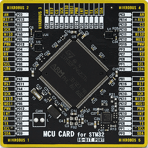
Microcontroller Overview
MCU Card / MCU
Type
8th Generation
Architecture
ARM Cortex-M7
MCU Memory (KB)
1024
Silicon Vendor
STMicroelectronics
Pin count
144
RAM (Bytes)
327680
Used MCU Pins
mikroBUS™ mapper
Take a closer look
Click board™ Schematic

Step by step
Project assembly

Start by selecting your development board and Click board™. Begin with the Fusion for STM32 v8 as your development board.


Software Support
Library Description
This library contains API for Hall Switch 2 Click driver.
Key functions:
hallswitch2_check_state- This function checks the S and N pin states, which indicates a magnetic field poles
Open Source
Code example
The complete application code and a ready-to-use project are available through the NECTO Studio Package Manager for direct installation in the NECTO Studio. The application code can also be found on the MIKROE GitHub account.
/*!
 * @file main.c
 * @brief Hall Switch 2 Click Example.
 *
 * # Description
 * This example demonstrates the use of Hall Switch 2 Click board.
 *
 * The demo application is composed of two sections :
 *
 * ## Application Init
 * Initializes the driver and logger and makes an initial log.
 *
 * ## Application Task
 * Displays the corresponding message on the USB UART based on the switches state,
 * i.e. based on the magnetic field presence.
 *
 * @author Stefan Filipovic
 *
 */

#include "board.h"
#include "log.h"
#include "hallswitch2.h"

static hallswitch2_t hallswitch2;   /**< Hall Switch 2 Click driver object. */
static log_t logger;                /**< Logger object. */
static uint8_t print_state = 0xFF;  /**< Starting case, any number above 2 should be good for our example. */

void application_init ( void )
{
    log_cfg_t log_cfg;                  /**< Logger config object. */
    hallswitch2_cfg_t hallswitch2_cfg;  /**< Click config object. */

    /**
     * Logger initialization.
     * Default baud rate: 115200
     * Default log level: LOG_LEVEL_DEBUG
     * @note If USB_UART_RX and USB_UART_TX
     * are defined as HAL_PIN_NC, you will
     * need to define them manually for log to work.
     * See @b LOG_MAP_USB_UART macro definition for detailed explanation.
     */
    LOG_MAP_USB_UART( log_cfg );
    log_init( &logger, &log_cfg );
    Delay_ms ( 100 );
    log_info( &logger, " Application Init " );

    // Click initialization.

    hallswitch2_cfg_setup( &hallswitch2_cfg );
    HALLSWITCH2_MAP_MIKROBUS( hallswitch2_cfg, MIKROBUS_1 );
    if ( hallswitch2_init( &hallswitch2, &hallswitch2_cfg ) == DIGITAL_OUT_UNSUPPORTED_PIN )
    {
        log_error( &logger, " Application Init Error. " );
        log_info( &logger, " Please, run program again... " );

        for ( ; ; );
    }
    log_info( &logger, " Application Task " );
}

void application_task ( void )
{
    switch ( hallswitch2_check_state( &hallswitch2 ) )
    {
        case HALLSWITCH2_NO_MAGNET_DETECTED:
        {
            if ( HALLSWITCH2_NO_MAGNET_DETECTED != print_state )
            {
                log_printf( &logger, " No magnet detected\r\n" );
                log_printf( &logger, " Switches - disabled\r\n\r\n" );
                print_state = HALLSWITCH2_NO_MAGNET_DETECTED;
            }
            break;
        }
        case HALLSWITCH2_S_POLE_DETECTED:
        {
            if ( HALLSWITCH2_S_POLE_DETECTED != print_state )
            {
                log_printf( &logger, " South pole detected\r\n" );
                log_printf( &logger, " Switch 1 - enabled\r\n\r\n" );
                print_state = HALLSWITCH2_S_POLE_DETECTED;
            }
            break;
        }
        case HALLSWITCH2_N_POLE_DETECTED:
        {
            if ( HALLSWITCH2_N_POLE_DETECTED != print_state )
            {
                log_printf( &logger, " North pole detected\r\n" );
                log_printf( &logger, " Switch 2 - enabled\r\n\r\n" );
                print_state = HALLSWITCH2_N_POLE_DETECTED;
            }
            break;
        }
        default:
        {
            break;
        }
    }
}

int main ( void )
{
    /* Do not remove this line or clock might not be set correctly. */
    #ifdef PREINIT_SUPPORTED
    preinit();
    #endif

    application_init( );

    for ( ; ; )
    {
        application_task( );
    }

    return 0;
}

// ------------------------------------------------------------------------ END
Additional Support
Resources
Category:Magnetic


