Achieve accurate and real-time positioning of objects in three-dimensional space with MLX90380 and PIC18F97J60
Magnetism mapped: 3D Hall sensor, your spatial intelligence

Published Sep 16, 2023
Click board™
3D Hall 6 Click
Dev. board
Fusion for PIC v8
Compiler
NECTO Studio
MCU
PIC18F97J60
Harness the power of 3D magnetic sensors to fortify your home's security, ensuring peace of mind with real-time intrusion detection and comprehensive surveillance.
A
A
Hardware Overview
How does it work?
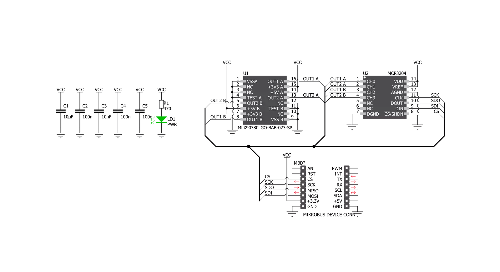
3D Hall 6 Click is based on the MLX90380, a monolithic contactless sensor IC sensitive to the flux density applied orthogonally and parallel to the IC surface, from Melexis. This sensor relies on a Hall effect to accurately sense magnetic field changes on three perpendicular axes. The internal magnetic field sensing elements are multiplexed and connected to a pre-amplifier and then to a sine and cosine analog outputs. All of the analog outptts are routed to the MCP3204 - onboard 4-channel 12-Bit A/D converter with SPI interface, from Microchip. The magnetic sensor has a very low pin count. However, in order to allow reading of the 4 analog inputs on the single Click board™, 3D Hall 6 click have onboard 4-channel, 12-Bit A/D converter, with SPI interface. Thus, the communication interface procedure relies on
reading the appropriate registers of the MCP3204. The MLX90380 contactless sensor also features a powerful programming engine, which allows the sensitivity and filter bandwidth to be programmed to optimally use the ADC input range of the ADC. However, because 3D Hall 6 click have onboard A/D converter, the output voltage of the MLX90380 is matched with the input range of the MCP3204, so the user don’t need to do any additional setting. High-speed dual analog outputs allow the MLX90380 to deliver accurate sine/cosine signals when used with a rotating permanent magnet. The sensor provides raw data output, based on a strength of the magnetic field. The measurement is affected by many factors: slight manufacturing differences between ICs affect the readings, even the slight differences
between Hall plates within the same IC might affect the accuracy, although the IC contains highly matched sensing elements. Also, the altitude might affect the readings, as well as temperature changes. The 3D Hall 6 software library contains simplified functions that allow straight-forward readings to be performed, reducing the steps needed for a proper initialization and configuration of the device. This Click board™ can be operated only with a 3.3V logic voltage level. The board must perform appropriate logic voltage level conversion before using MCUs with different logic levels. Also, it comes equipped with a library containing functions and an example code that can be used as a reference for further development.


Features overview
Development board
Fusion for PIC v8 is a development board specially designed for the needs of rapid development of embedded applications. It supports a wide range of microcontrollers, such as different PIC, dsPIC, PIC24, and PIC32 MCUs regardless of their number of pins, and a broad set of unique functions, such as the first-ever embedded debugger/programmer over WiFi. The development board is well organized and designed so that the end-user has all the necessary elements, such as switches, buttons, indicators, connectors, and others, in one place. Thanks to innovative manufacturing technology, Fusion for PIC v8 provides a fluid and immersive working experience, allowing access anywhere and under any
circumstances at any time. Each part of the Fusion for PIC v8 development board contains the components necessary for the most efficient operation of the same board. In addition to the advanced integrated CODEGRIP programmer/debugger module, which offers many valuable programming/debugging options and seamless integration with the Mikroe software environment, the board also includes a clean and regulated power supply module for the development board. It can use a wide range of external power sources, including a battery, an external 12V power supply, and a power source via the USB Type-C (USB-C) connector. Communication options such as USB-UART, USB
HOST/DEVICE, CAN (on the MCU card, if supported), and Ethernet are also included, including the well-established mikroBUS™ standard, a standardized socket for the MCU card (SiBRAIN standard), and two display options (graphical and character-based LCD). Fusion for PIC v8 is an integral part of the Mikroe ecosystem for rapid development. Natively supported by Mikroe software tools, it covers many aspects of prototyping and development thanks to a considerable number of different Click boards™ (over a thousand boards), the number of which is growing every day.

Microcontroller Overview
MCU Card / MCU
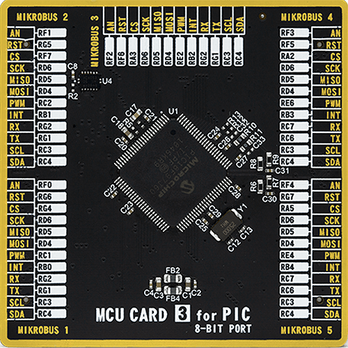
Type
8th Generation
Architecture
PIC
MCU Memory (KB)
128
Silicon Vendor
Microchip
Pin count
100
RAM (Bytes)
3808
Used MCU Pins
mikroBUS™ mapper
Take a closer look
Click board™ Schematic
Step by step
Project assembly

Start by selecting your development board and Click board™. Begin with the Fusion for PIC v8 as your development board.


Software Support
Library Description
This library contains API for 3D Hall 6 Click driver.
Key functions:
c3dhall6_set_reference_values- This function sets reference values for voltage and angle calculationsc3dhall6_get_adc_value- This function reads ADC value on selected channelc3dhall6_get_volt- This function reads ADC value on selected channel and converts that value to Volts or miliVolts - depending on reference voltage setting.
Open Source
Code example
The complete application code and a ready-to-use project are available through the NECTO Studio Package Manager for direct installation in the NECTO Studio. The application code can also be found on the MIKROE GitHub account.
/*!
 * \file
 * \brief 3dHall6 Click example
 *
 * # Description
 * This application measure the intensity of the magnetic field across three perpendicular axes.
 *
 * The demo application is composed of two sections :
 *
 * ## Application Init
 * Initializes device.
 *
 * ## Application Task
 *  Executes one or more 'c3dhall6_log_xxx_task' functions
 *
 *  Additional Functions :
 *
 *  - c3dhall6_log_adc_task() - performs and logs adc measurements on all channels
 *  - c3dhall6_log_volt_task() - performs and logs voltage measurements on all channels
 *  - c3dhall6_log_angle_rad_task() - performs and logs angle measurements in radians on each die
 *  - c3dhall6_log_angle_deg_task() - performs and logs angle measurements in degrees on each die
 *
 * \author MikroE Team
 *
 */
// ------------------------------------------------------------------- INCLUDES

#include "board.h"
#include "log.h"
#include "c3dhall6.h"

// ------------------------------------------------------------------ VARIABLES

static c3dhall6_t c3dhall6;
static log_t logger;

// ------------------------------------------------------- ADDITIONAL FUNCTIONS

static void c3dhall6_log_adc_task( )
{
    uint16_t ch0_adc_value;
    uint16_t ch1_adc_value;
    uint16_t ch2_adc_value;
    uint16_t ch3_adc_value;

    c3dhall6_get_adc_value( &c3dhall6, C3DHALL6_CHANNEL_0, &ch0_adc_value );
    c3dhall6_get_adc_value( &c3dhall6, C3DHALL6_CHANNEL_1, &ch1_adc_value );
    c3dhall6_get_adc_value( &c3dhall6, C3DHALL6_CHANNEL_2, &ch2_adc_value );
    c3dhall6_get_adc_value( &c3dhall6, C3DHALL6_CHANNEL_3, &ch3_adc_value );

    log_printf( &logger, "ADC on CH0 : %u \r\n", ch0_adc_value );
    log_printf( &logger, "ADC on CH1 : %u \r\n", ch1_adc_value );
    log_printf( &logger, "ADC on CH2 : %u \r\n", ch2_adc_value );
    log_printf( &logger, "ADC on CH3 : %u \r\n", ch3_adc_value );
}

void c3dhall6_log_volt_task( )
{
    float ch0_voltage;
    float ch1_voltage;
    float ch2_voltage;
    float ch3_voltage;

    c3dhall6_get_volt( &c3dhall6, C3DHALL6_CHANNEL_0, &ch0_voltage );
    c3dhall6_get_volt( &c3dhall6, C3DHALL6_CHANNEL_1, &ch1_voltage );
    c3dhall6_get_volt( &c3dhall6, C3DHALL6_CHANNEL_2, &ch2_voltage );
    c3dhall6_get_volt( &c3dhall6, C3DHALL6_CHANNEL_3, &ch3_voltage );

    log_printf( &logger, "Voltage on CH0 : %.3f V \r\n", ch0_voltage );
    log_printf( &logger, "Voltage on CH1 : %.3f V \r\n", ch1_voltage );
    log_printf( &logger, "Voltage on CH2 : %.3f V \r\n", ch2_voltage );
    log_printf( &logger, "Voltage on CH3 : %.3f V \r\n", ch3_voltage );
}

void c3dhall6_log_angle_rad_task( )
{
    float die_a_angle;
    float die_b_angle;

    c3dhall6_get_angle_rad( &c3dhall6, C3DHALL6_DIE_A, &die_a_angle );
    c3dhall6_get_angle_rad( &c3dhall6, C3DHALL6_DIE_B, &die_b_angle );

    log_printf( &logger, "DIE A Angle value :  %.1f rad \r\n", die_a_angle );
    log_printf( &logger, "DIE B Angle value :  %.1f rad \r\n", die_b_angle );
}

void c3dhall6_log_angle_deg_task( )
{
    float die_a_angle;
    float die_b_angle;

    c3dhall6_get_angle_deg( &c3dhall6, C3DHALL6_DIE_A, &die_a_angle );
    c3dhall6_get_angle_deg( &c3dhall6, C3DHALL6_DIE_B, &die_b_angle );

    log_printf( &logger, "DIE A Angle value :  %.1f deg \r\n", die_a_angle );
    log_printf( &logger, "DIE B Angle value :  %.1f deg \r\n", die_b_angle );

}

// ------------------------------------------------------ APPLICATION FUNCTIONS

void application_init ( void )
{
    log_cfg_t log_cfg;
    c3dhall6_cfg_t cfg;

    /**
     * Logger initialization.
     * Default baud rate: 115200
     * Default log level: LOG_LEVEL_DEBUG
     * @note If USB_UART_RX and USB_UART_TX
     * are defined as HAL_PIN_NC, you will
     * need to define them manually for log to work.
     * See @b LOG_MAP_USB_UART macro definition for detailed explanation.
     */
    LOG_MAP_USB_UART( log_cfg );
    log_init( &logger, &log_cfg );
    log_info( &logger, " Application Init " );

    // Click initialization.
    c3dhall6_cfg_setup( &cfg );
    C3DHALL6_MAP_MIKROBUS( cfg, MIKROBUS_1 );
    c3dhall6_init( &c3dhall6, &cfg );

    c3dhall6_aux_ref_t ref_val =
    {
        .aux_ref_adc_ch0 = 2048.0,
        .aux_ref_adc_ch1 = 2048.0,
        .aux_ref_adc_ch2 = 2048.0,
        .aux_ref_adc_ch3 = 2048.0,
        .aux_ref_volt = 3.3
    };
    c3dhall6_set_reference_values( &c3dhall6, ref_val );

    log_info( &logger, " Application Task " );
}

void application_task ( void )
{
    c3dhall6_log_angle_deg_task( );
    Delay_ms ( 1000 );
}

int main ( void )
{
    /* Do not remove this line or clock might not be set correctly. */
    #ifdef PREINIT_SUPPORTED
    preinit();
    #endif

    application_init( );

    for ( ; ; )
    {
        application_task( );
    }

    return 0;
}


// ------------------------------------------------------------------------ END
Additional Support
Resources
Category:Magnetic


