Expand I/O capabilities and streamline data management with PCAL6524 and STM32L496AG
Versatile I/O expansion: Unlock I/O potential with ease!
Published Jul 22, 2025
Click board™
Expand 10 Click
Dev. board
Discovery kit with STM32L496AG MCU
Compiler
NECTO Studio
MCU
STM32L496AG
Transform your electronics design with our I/O expansion solution, offering a reliable and efficient means for connecting and controlling a wide range of devices and peripherals
A
A
Hardware Overview
How does it work?
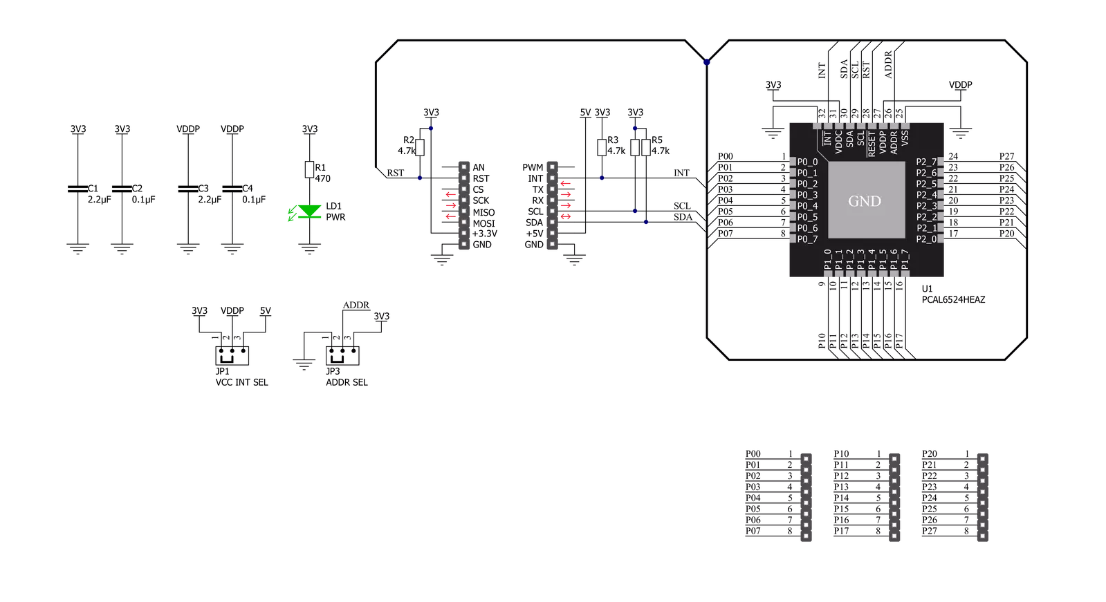
Expand 10 Click is based on the PCAL6524, a 24-bit ultra-low-voltage translating general-purpose I/O expander from NXP Semiconductors. This port expander is a simple solution for when additional I/Os are needed while keeping interconnections to a minimum. It is particularly great for system monitoring applications, industrial controllers, and portable equipment. The PCAL6524 has a built-in level shifting feature that makes it highly flexible in power supply systems where communication between incompatible I/O voltages is required. The PCAL6524 implements Agile I/O features designed to enhance the I/O. These additional features are programmable output drive strength, latchable inputs, programmable
pull-up/pull-down resistors, maskable interrupt, interrupt status register, and programmable open-drain or push-pull outputs. Expand 10 Click communicates with MCU using the standard I2C 2-Wire interface to read data and configure settings, supporting a Fast Mode Plus operation up to 1MHz. At the Power-On sequence, the I/Os are configured as inputs. However, the host MCU can enable the I/Os as inputs or outputs by writing to the I/O configuration bits. In addition to I2C communication, two GPIO pins connected to the mikroBUS™ socket pins are also used. The reset pin routed to the RST pin of the mikroBUS™ socket, is used to place the PCAL6524 registers in their default state, while the interrupt, routed
to the INT pin of the mikroBUS™ socket, may be configured as an interrupt to notify the host MCU of incoming data on any port. Besides, it also allows the choice of the least significant bit of its I2C slave address by positioning the SMD jumper labeled ADDR SEL to an appropriate position marked as 1 and 0. This Click board™ can operate with either 3.3V or 5V logic voltage levels selected via the VCC SEL jumper. This way, both 3.3V and 5V capable MCUs can use the communication lines properly. Also, this Click board™ comes equipped with a library containing easy-to-use functions and an example code that can be used as a reference for further development.


Features overview
Development board
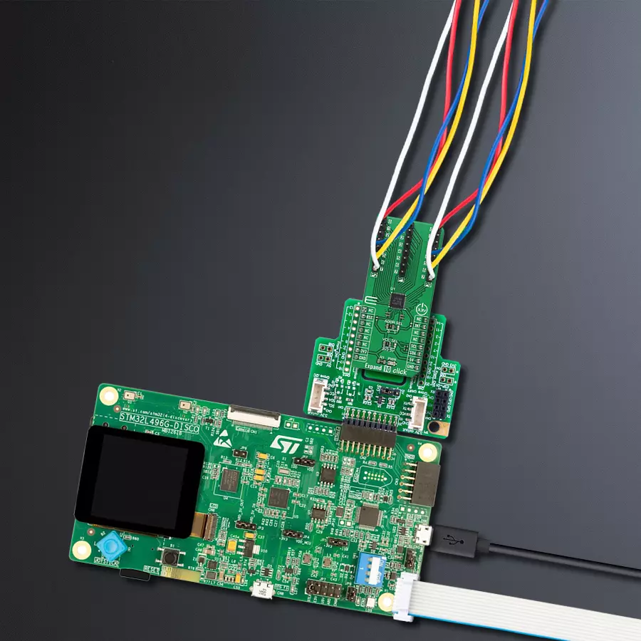
The 32L496GDISCOVERY Discovery kit serves as a comprehensive demonstration and development platform for the STM32L496AG microcontroller, featuring an Arm® Cortex®-M4 core. Designed for applications that demand a balance of high performance, advanced graphics, and ultra-low power consumption, this kit enables seamless prototyping for a wide range of embedded solutions. With its innovative energy-efficient
architecture, the STM32L496AG integrates extended RAM and the Chrom-ART Accelerator, enhancing graphics performance while maintaining low power consumption. This makes the kit particularly well-suited for applications involving audio processing, graphical user interfaces, and real-time data acquisition, where energy efficiency is a key requirement. For ease of development, the board includes an onboard ST-LINK/V2-1
debugger/programmer, providing a seamless out-of-the-box experience for loading, debugging, and testing applications without requiring additional hardware. The combination of low power features, enhanced memory capabilities, and built-in debugging tools makes the 32L496GDISCOVERY kit an ideal choice for prototyping advanced embedded systems with state-of-the-art energy efficiency.

Microcontroller Overview
MCU Card / MCU

Architecture
ARM Cortex-M4
MCU Memory (KB)
1024
Silicon Vendor
STMicroelectronics
Pin count
169
RAM (Bytes)
327680
Used MCU Pins
mikroBUS™ mapper
Take a closer look
Click board™ Schematic
Step by step
Project assembly

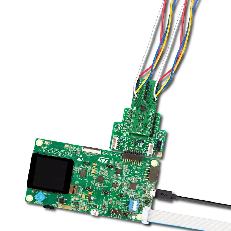
Start by selecting your development board and Click board™. Begin with the Discovery kit with STM32L496AG MCU as your development board.


Track your results in real time
Application Output
1. Application Output - In Debug mode, the 'Application Output' window enables real-time data monitoring, offering direct insight into execution results. Ensure proper data display by configuring the environment correctly using the provided tutorial.

2. UART Terminal - Use the UART Terminal to monitor data transmission via a USB to UART converter, allowing direct communication between the Click board™ and your development system. Configure the baud rate and other serial settings according to your project's requirements to ensure proper functionality. For step-by-step setup instructions, refer to the provided tutorial.

3. Plot Output - The Plot feature offers a powerful way to visualize real-time sensor data, enabling trend analysis, debugging, and comparison of multiple data points. To set it up correctly, follow the provided tutorial, which includes a step-by-step example of using the Plot feature to display Click board™ readings. To use the Plot feature in your code, use the function: plot(*insert_graph_name*, variable_name);. This is a general format, and it is up to the user to replace 'insert_graph_name' with the actual graph name and 'variable_name' with the parameter to be displayed.

Software Support
Library Description
This library contains API for Expand 10 Click driver.
Key functions:
expand10_set_pin_direction- This function sets the direction of the selected pinsexpand10_set_pin_value- This function sets the value of the selected pinsexpand10_read_port_value- This function reads the value of the selected port input pins
Open Source
Code example
The complete application code and a ready-to-use project are available through the NECTO Studio Package Manager for direct installation in the NECTO Studio. The application code can also be found on the MIKROE GitHub account.
/*!
 * @file main.c
 * @brief Expand10 Click example
 *
 * # Description
 * This example demonstrates the use of Expand 10 Click board.
 *
 * The demo application is composed of two sections :
 *
 * ## Application Init
 * Initializes the driver and performs the Click default configuration which sets the first two ports
 * as output and the third port as input with pull-down enabled.
 *
 * ## Application Task
 * Sets the pins of the first two ports and then reads and displays the status of
 * all ports on the USB UART approximately once per second.
 *
 * @author Stefan Filipovic
 *
 */

#include "board.h"
#include "log.h"
#include "expand10.h"

static expand10_t expand10;
static log_t logger;

void application_init ( void )
{
    log_cfg_t log_cfg;            /**< Logger config object. */
    expand10_cfg_t expand10_cfg;  /**< Click config object. */

    /**
     * Logger initialization.
     * Default baud rate: 115200
     * Default log level: LOG_LEVEL_DEBUG
     * @note If USB_UART_RX and USB_UART_TX
     * are defined as HAL_PIN_NC, you will
     * need to define them manually for log to work.
     * See @b LOG_MAP_USB_UART macro definition for detailed explanation.
     */
    LOG_MAP_USB_UART( log_cfg );
    log_init( &logger, &log_cfg );
    log_info( &logger, " Application Init " );

    // Click initialization.
    expand10_cfg_setup( &expand10_cfg );
    EXPAND10_MAP_MIKROBUS( expand10_cfg, MIKROBUS_1 );
    err_t init_flag = expand10_init( &expand10, &expand10_cfg );
    if ( I2C_MASTER_ERROR == init_flag )
    {
        log_error( &logger, " Application Init Error. " );
        log_info( &logger, " Please, run program again... " );
        for ( ; ; );
    }

    init_flag = expand10_default_cfg ( &expand10 );
    if ( EXPAND10_ERROR == init_flag )
    {
        log_error( &logger, " Default Config Error. " );
        log_info( &logger, " Please, run program again... " );
        for ( ; ; );
    }

    log_info( &logger, " Application Task " );
}

void application_task ( void )
{
    uint8_t port_value = 0;

    for ( uint16_t pin_num = EXPAND10_PIN_0_MASK; pin_num <= EXPAND10_PIN_7_MASK; pin_num <<= 1 )
    {
        expand10_set_all_pins_value( &expand10, pin_num );

        expand10_read_port_value( &expand10, EXPAND10_PORT_0, &port_value );
        log_printf( &logger, " Status P0 (output): 0x%.2X\r\n", ( uint16_t ) port_value );

        expand10_read_port_value( &expand10, EXPAND10_PORT_1, &port_value );
        log_printf( &logger, " Status P1 (output): 0x%.2X\r\n", ( uint16_t ) port_value );

        expand10_read_port_value( &expand10, EXPAND10_PORT_2, &port_value );
        log_printf( &logger, " Status P2 (input) : 0x%.2X\r\n\r\n", ( uint16_t ) port_value );
        Delay_ms ( 1000 );
    }
}

int main ( void )
{
    /* Do not remove this line or clock might not be set correctly. */
    #ifdef PREINIT_SUPPORTED
    preinit();
    #endif

    application_init( );

    for ( ; ; )
    {
        application_task( );
    }

    return 0;
}

// ------------------------------------------------------------------------ END
Additional Support
Resources
Category:Port expander