Expand the number of input/output pins in your project with TCAL6408 and STM32H743ZI
8-bit I/O expander with interrupt, reset, and agile I/O
Published Jul 22, 2025
Click board™
Expand 17 Click
Dev. board
Nucleo 144 with STM32H743ZI MCU
Compiler
NECTO Studio
MCU
STM32H743ZI
Add more input and output pins to your project for increased functionality
A
A
Hardware Overview
How does it work?
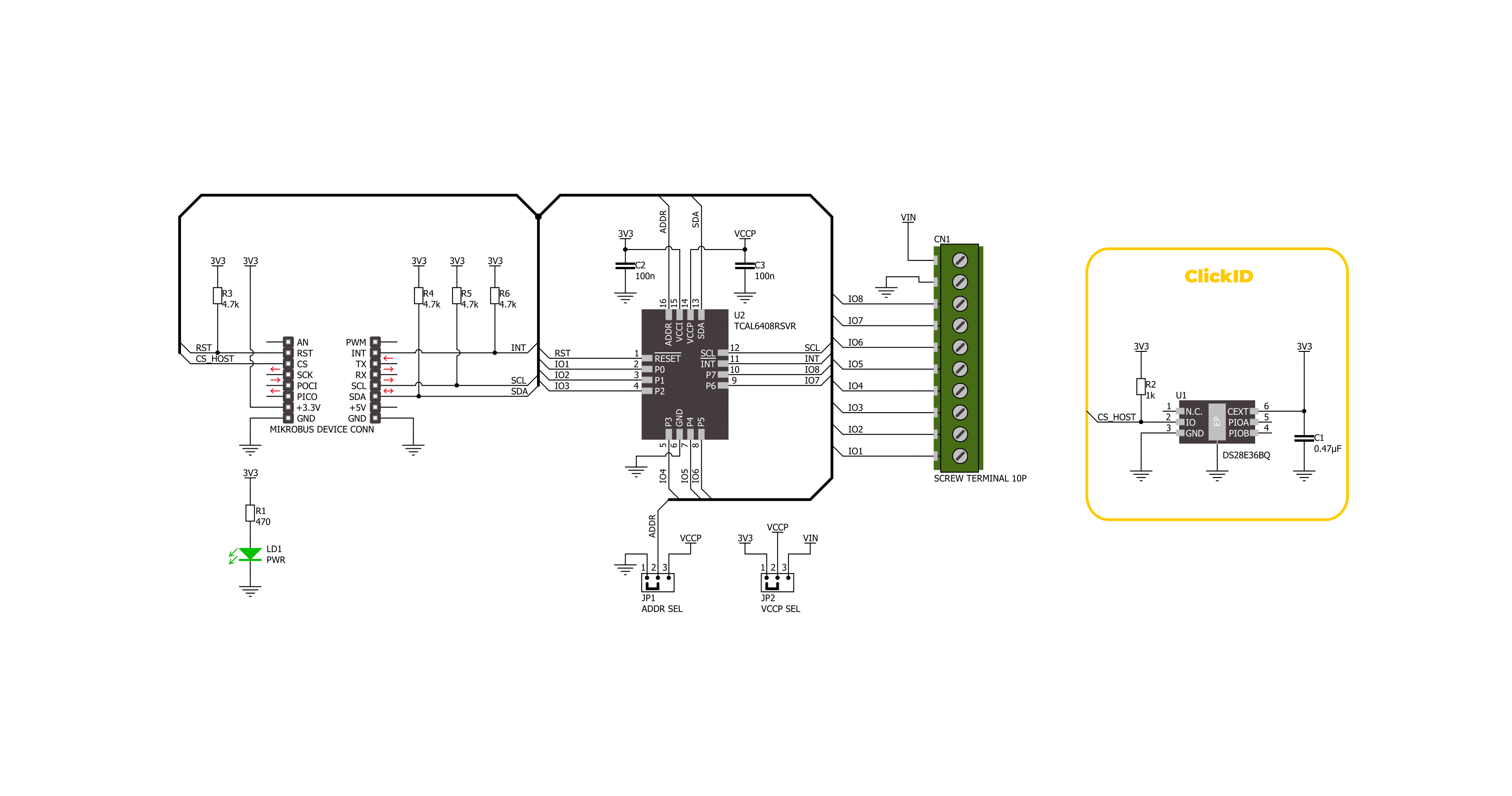
Expand 17 Click is based on the TCAL6408, an 8-bit I/O expander from Texas Instruments designed to provide input/output expansion through the I2C protocol. This Click board™ offers an ideal solution for adding more I/Os to the system when dealing with switches, sensors, push-buttons, LEDs, fans, and other peripherals. The TCAL6408 IC features agile I/O configuration registers, providing programmable output drive strength, latchable inputs, maskable interrupts, programmable pull-up/down resistors, and the ability to configure open-drain or push-pull outputs. These advanced features ensure enhanced I/O performance with improved speed, power consumption, and reduced
electromagnetic interference (EMI). The TCAL6408 supports independent logic and power supplies. The logic voltage is supplied via the 3.3V mikroBUS™ power rail, while the main power can be selected between 3.3V from the mikroBUS™ or an externally provided supply through the VIN terminal, with a range of 1.08V to 3.6V. The main power selection is managed by the VCCP SEL jumper, allowing users to set the appropriate power source for the TCAL6408 based on their application's requirements. Expand 17 Click communicates with the host MCU via the standard 2-wire I2C interface, supporting clock frequencies up to 1MHz. The I2C address is easily configurable
using the onboard ADDR SEL jumper. Additionally, this board also uses an active-low reset (RST) pin, used for initializing the device, and an open-drain active-low interrupt (INT) pin, which provides notification of changes in input status, ensuring efficient handling of external events and inputs. This Click board™ can be operated only with a 3.3V logic voltage level. The board must perform appropriate logic voltage level conversion before using MCUs with different logic levels. Also, it comes equipped with a library containing functions and an example code that can be used as a reference for further development.

Features overview
Development board
Nucleo-144 with STM32H743ZI MCU board offers an accessible and adaptable avenue for users to explore new ideas and construct prototypes. It allows users to tailor their experience by selecting from a range of performance and power consumption features offered by the STM32 microcontroller. With compatible boards, the
internal or external SMPS dramatically decreases power usage in Run mode. Including the ST Zio connector, expanding ARDUINO Uno V3 connectivity, and ST morpho headers facilitate easy expansion of the Nucleo open development platform. The integrated ST-LINK debugger/programmer enhances convenience by
eliminating the need for a separate probe. Moreover, the board is accompanied by comprehensive free software libraries and examples within the STM32Cube MCU Package, further enhancing its utility and value.

Microcontroller Overview
MCU Card / MCU
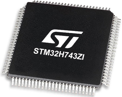
Architecture
ARM Cortex-M7
MCU Memory (KB)
2048
Silicon Vendor
STMicroelectronics
Pin count
144
RAM (Bytes)
1048576
You complete me!
Accessories
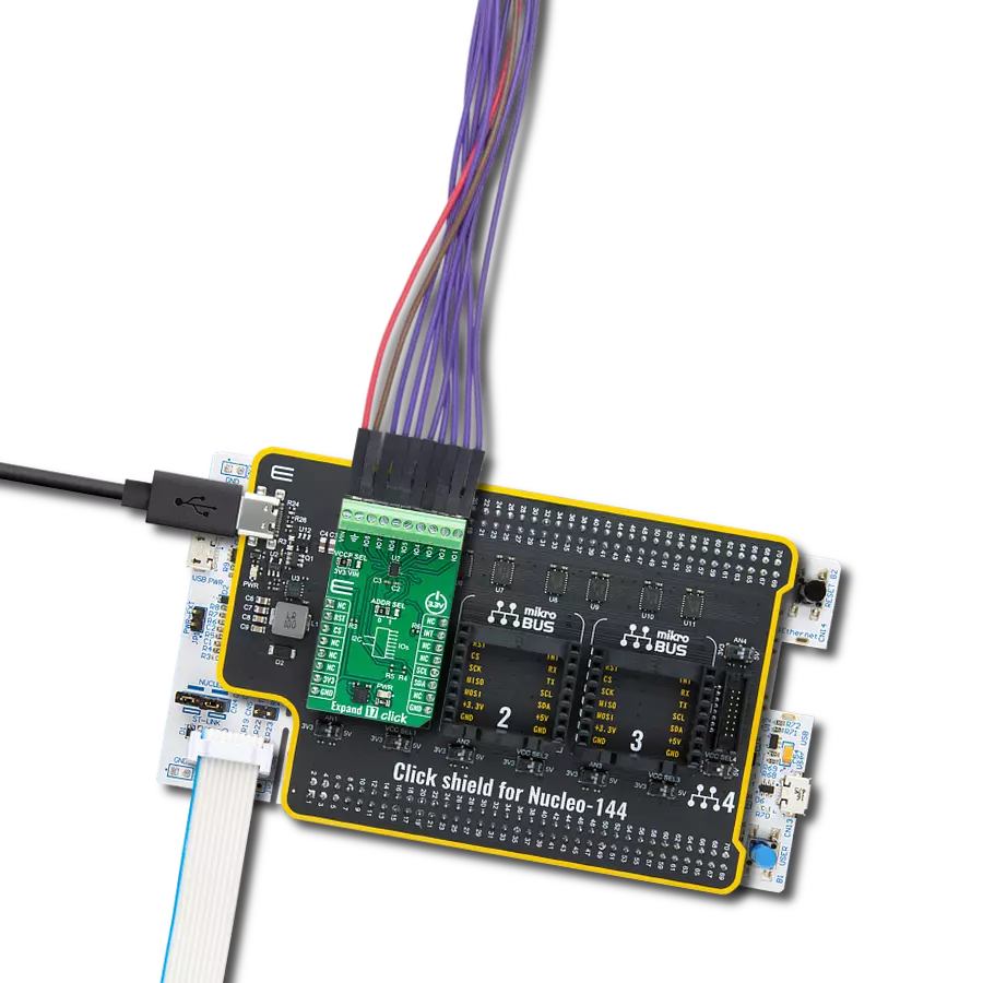
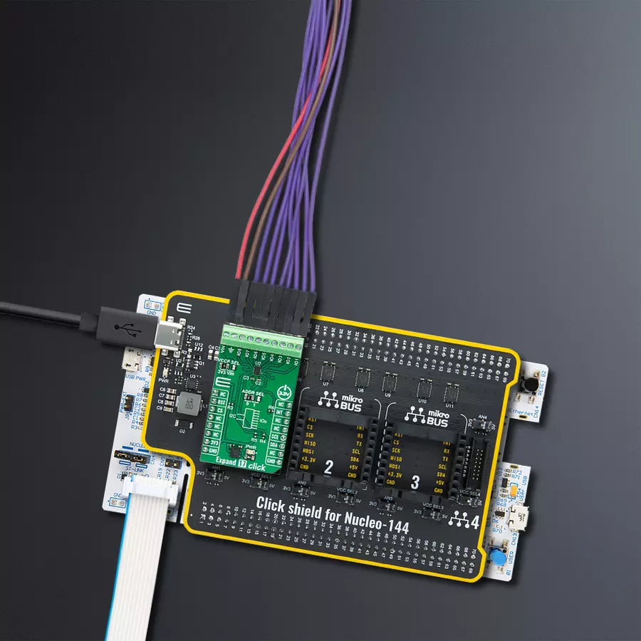
Click Shield for Nucleo-144 comes equipped with four mikroBUS™ sockets, with one in the form of a Shuttle connector, allowing all the Click board™ devices to be interfaced with the STM32 Nucleo-144 board with no effort. This way, MIKROE allows its users to add any functionality from our ever-growing range of Click boards™, such as WiFi, GSM, GPS, Bluetooth, ZigBee, environmental sensors, LEDs, speech recognition, motor control, movement sensors, and many more. Featuring an ARM Cortex-M microcontroller, 144 pins, and Arduino™ compatibility, the STM32 Nucleo-144 board offers limitless possibilities for prototyping and creating diverse applications. These boards are controlled and powered conveniently through a USB connection to program and efficiently debug the Nucleo-144 board out of the box, with an additional USB cable connected to the USB mini port on the board. Simplify your project development with the integrated ST-Link debugger and unleash creativity using the extensive I/O options and expansion capabilities. This Click Shield also has several switches that perform functions such as selecting the logic levels of analog signals on mikroBUS™ sockets and selecting logic voltage levels of the mikroBUS™ sockets themselves. Besides, the user is offered the possibility of using any Click board™ with the help of existing bidirectional level-shifting voltage translators, regardless of whether the Click board™ operates at a 3.3V or 5V logic voltage level. Once you connect the STM32 Nucleo-144 board with our Click Shield for Nucleo-144, you can access hundreds of Click boards™, working with 3.3V or 5V logic voltage levels.

Used MCU Pins
mikroBUS™ mapper
Take a closer look
Click board™ Schematic
Step by step
Project assembly
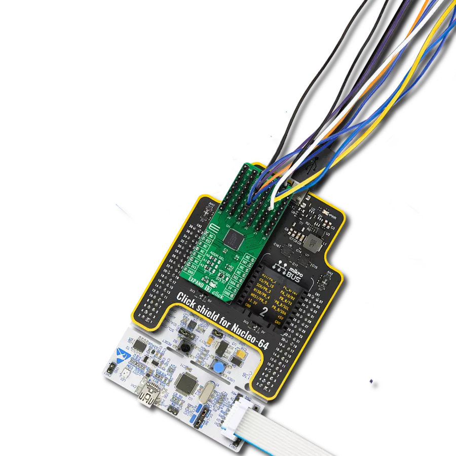
Start by selecting your development board and Click board™. Begin with the Nucleo 144 with STM32H743ZI MCU as your development board.


Track your results in real time
Application Output
1. Application Output - In Debug mode, the 'Application Output' window enables real-time data monitoring, offering direct insight into execution results. Ensure proper data display by configuring the environment correctly using the provided tutorial.

2. UART Terminal - Use the UART Terminal to monitor data transmission via a USB to UART converter, allowing direct communication between the Click board™ and your development system. Configure the baud rate and other serial settings according to your project's requirements to ensure proper functionality. For step-by-step setup instructions, refer to the provided tutorial.

3. Plot Output - The Plot feature offers a powerful way to visualize real-time sensor data, enabling trend analysis, debugging, and comparison of multiple data points. To set it up correctly, follow the provided tutorial, which includes a step-by-step example of using the Plot feature to display Click board™ readings. To use the Plot feature in your code, use the function: plot(*insert_graph_name*, variable_name);. This is a general format, and it is up to the user to replace 'insert_graph_name' with the actual graph name and 'variable_name' with the parameter to be displayed.

Software Support
Library Description
This library contains API for Expand 17 Click driver.
Key functions:
expand17_set_io_dir- This function is used to set input or output direction of pins.expand17_set_output_state- This function is used to set output state of the pins.expand17_get_input_state- This function is used to get state of the input pins.
Open Source
Code example
The complete application code and a ready-to-use project are available through the NECTO Studio Package Manager for direct installation in the NECTO Studio. The application code can also be found on the MIKROE GitHub account.
/*!
 * @file main.c
 * @brief Expand 17 Click example
 *
 * # Description
 * This example demonstrates the use of Expand 17 Click board by setting and reading
 * the ports state.
 *
 * The demo application is composed of two sections :
 *
 * ## Application Init
 * Initializes the driver and performs the Click default configuration which sets
 * half of pins as output ( IO5, IO6, IO7 and IO8 ) and the
 * half of the pins as inputs ( IO1, IO2, IO3 and IO4 ).
 *
 * ## Application Task
 * Sets the state of the output pins and then reads the status of the input pins
 * and displays the results on the USB UART approximately every 2 seconds.
 *
 * @note
 * In order for this example to work as intended it is necessary to connect the input and output pins
 * eg. IO1 and IO5, IO2 and IO6 etc. Floating input pins will be shown as a high state.
 *
 * @author Stefan Ilic
 *
 */

#include "board.h"
#include "log.h"
#include "expand17.h"

static expand17_t expand17;
static log_t logger;

void application_init ( void )
{
    log_cfg_t log_cfg;  /**< Logger config object. */
    expand17_cfg_t expand17_cfg;  /**< Click config object. */

    /**
     * Logger initialization.
     * Default baud rate: 115200
     * Default log level: LOG_LEVEL_DEBUG
     * @note If USB_UART_RX and USB_UART_TX
     * are defined as HAL_PIN_NC, you will
     * need to define them manually for log to work.
     * See @b LOG_MAP_USB_UART macro definition for detailed explanation.
     */
    LOG_MAP_USB_UART( log_cfg );
    log_init( &logger, &log_cfg );
    log_info( &logger, " Application Init " );

    // Click initialization.
    expand17_cfg_setup( &expand17_cfg );
    EXPAND17_MAP_MIKROBUS( expand17_cfg, MIKROBUS_1 );
    if ( I2C_MASTER_ERROR == expand17_init( &expand17, &expand17_cfg ) )
    {
        log_error( &logger, " Communication init." );
        for ( ; ; );
    }

    if ( EXPAND17_ERROR == expand17_default_cfg ( &expand17 ) )
    {
        log_error( &logger, " Default configuration." );
        for ( ; ; );
    }

    log_info( &logger, " Application Task " );
}

void application_task ( void )
{
    uint8_t input_state = 0;

    log_printf( &logger, " Setting output pins state: HIGH \r\n" );
    log_printf( &logger, " = = = = = = = = = = = = = = = = = \r\n" );
    expand17_set_output_state( &expand17, EXPAND17_NO_IO_PIN_MASK, EXPAND17_IO_5_PIN_MASK |
                                          EXPAND17_IO_6_PIN_MASK | EXPAND17_IO_7_PIN_MASK |
                                          EXPAND17_IO_8_PIN_MASK );

    log_printf( &logger, " State of input pins: \r\n" );
    log_printf( &logger, " = = = = = = = = = = = = = = = = = \r\n" );
    expand17_get_input_state( &expand17, &input_state );
    if ( input_state & EXPAND17_IO_1_PIN_MASK )
    {
        log_printf( &logger, " IO1 - HIGH \r\n" );
    }
    else
    {
        log_printf( &logger, " IO1 - LOW \r\n" );
    }
    if ( input_state & EXPAND17_IO_2_PIN_MASK )
    {
        log_printf( &logger, " IO2 - HIGH \r\n" );
    }
    else
    {
        log_printf( &logger, " IO2 - LOW \r\n" );
    }
    if ( input_state & EXPAND17_IO_3_PIN_MASK )
    {
        log_printf( &logger, " IO3 - HIGH \r\n" );
    }
    else
    {
        log_printf( &logger, " IO3 - LOW \r\n" );
    }
    if ( input_state & EXPAND17_IO_4_PIN_MASK )
    {
        log_printf( &logger, " IO4 - HIGH \r\n" );
    }
    else
    {
        log_printf( &logger, " IO4 - LOW \r\n" );
    }
    log_printf( &logger, " = = = = = = = = = = = = = = = = = \r\n" );
    Delay_ms ( 1000 );
    Delay_ms ( 1000 );

    log_printf( &logger, " Setting output pins state: LOW \r\n" );
    log_printf( &logger, " = = = = = = = = = = = = = = = = = \r\n" );
    expand17_set_output_state( &expand17, EXPAND17_IO_5_PIN_MASK | EXPAND17_IO_6_PIN_MASK |
                                          EXPAND17_IO_7_PIN_MASK | EXPAND17_IO_8_PIN_MASK,
                                          EXPAND17_NO_IO_PIN_MASK );

    log_printf( &logger, " State of input pins: \r\n" );
    log_printf( &logger, " = = = = = = = = = = = = = = = = = \r\n" );
    expand17_get_input_state( &expand17, &input_state );
    if ( input_state & EXPAND17_IO_1_PIN_MASK )
    {
        log_printf( &logger, " IO1 - HIGH \r\n" );
    }
    else
    {
        log_printf( &logger, " IO1 - LOW \r\n" );
    }
    if ( input_state & EXPAND17_IO_2_PIN_MASK )
    {
        log_printf( &logger, " IO2 - HIGH \r\n" );
    }
    else
    {
        log_printf( &logger, " IO2 - LOW \r\n" );
    }
    if ( input_state & EXPAND17_IO_3_PIN_MASK )
    {
        log_printf( &logger, " IO3 - HIGH \r\n" );
    }
    else
    {
        log_printf( &logger, " IO3 - LOW \r\n" );
    }
    if ( input_state & EXPAND17_IO_4_PIN_MASK )
    {
        log_printf( &logger, " IO4 - HIGH \r\n" );
    }
    else
    {
        log_printf( &logger, " IO4 - LOW \r\n" );
    }
    log_printf( &logger, " = = = = = = = = = = = = = = = = = \r\n" );
    Delay_ms ( 1000 );
    Delay_ms ( 1000 );
}

int main ( void )
{
    /* Do not remove this line or clock might not be set correctly. */
    #ifdef PREINIT_SUPPORTED
    preinit();
    #endif

    application_init( );

    for ( ; ; )
    {
        application_task( );
    }

    return 0;
}

// ------------------------------------------------------------------------ END
Additional Support
Resources
Category:Port expander