Achieve accurate and reliable AC/DC current sensing with TLI4970-D050T4 and TM4C129ENCPDT
Coreless magnetic current sensor for currents up to ±25A
Published Jun 19, 2023
Click board™
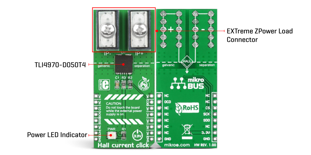
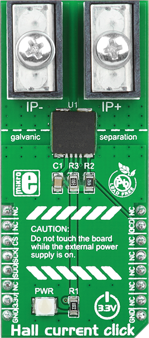
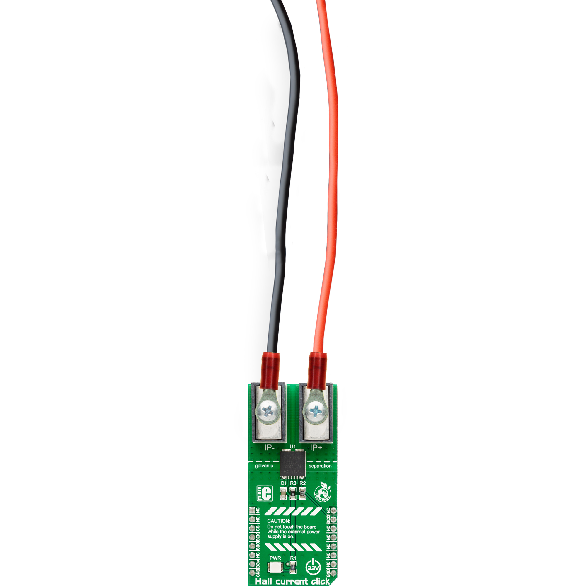
Hall Current Click
Dev. board
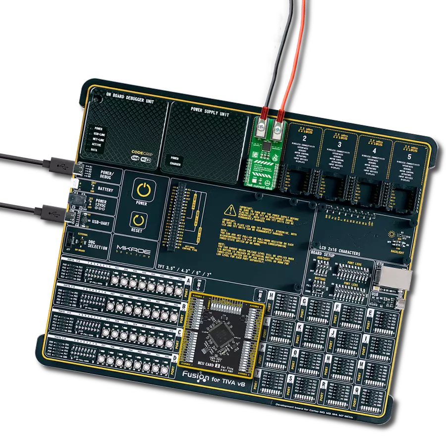
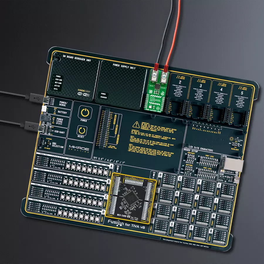
Fusion for Tiva v8
Compiler
NECTO Studio
MCU
TM4C129ENCPDT
AC/DC current sensor utilizing Hall technology, capable of measuring up to ±25A and certified according to industrial standards, ideal for use in both industrial and consumer applications
A
A
Hardware Overview
How does it work?
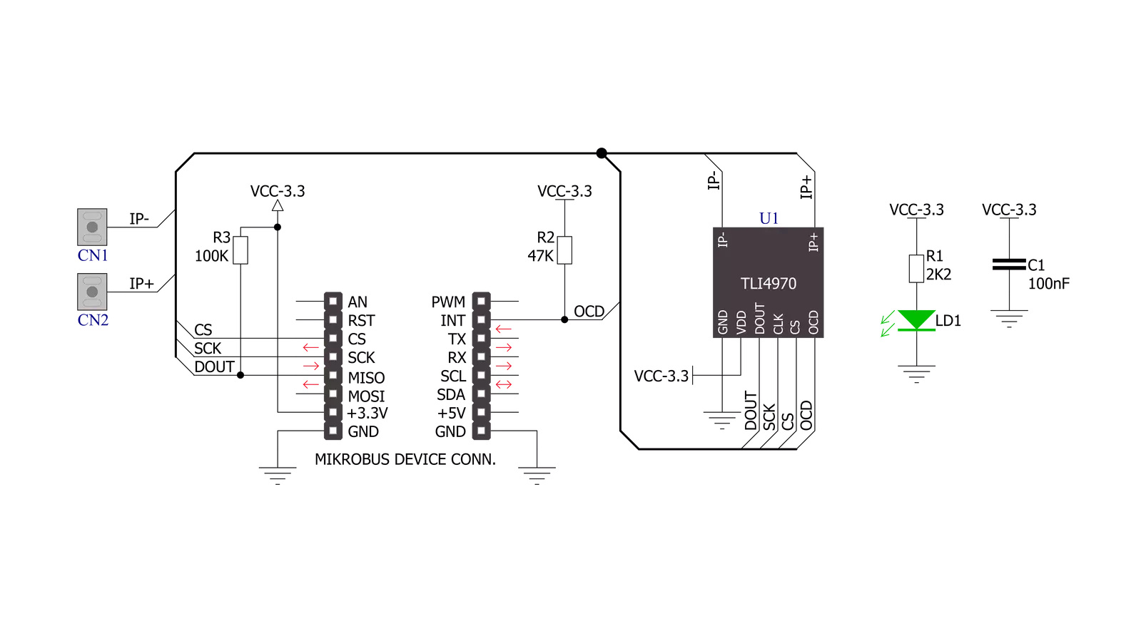
Hall Current Click is based on the TLI4970-D050T4, a high-precision digital current sensor designed for the current range of ±25A from Infineon Technology. The measurement principle allows galvanic isolation (functional isolation) between the primary conductor and the secondary interface. Based on a digital concept, the signal processing unit of the TLI4970-D050T4 already has integrated compensation and calibration, which means no further external measurements for compensation are needed. It represents a plug-and-play solution, easy to use in industrial and consumer applications. The differential measurement principle of the TLI4970-D050T4 achieves best-in-class suppression of stray magnetic fields with a highly linear output signal
without hysteresis. The accuracy of the TLI4970-D050T4 is comparable to closed-loop current measurement systems and even better than open-loop systems with magnetic cores. But in comparison to the open- and closed-loop systems, the TLI4970-D050T4 enables significantly less power consumption. Besides outstanding long-term stability of the output signal and a proprietary dynamic offset cancellation technique that guarantees low zero point error, the TLI4970-D050T4 offers superior performance. As mentioned, this Click board™ communicates with MCU through a standard unidirectional 16-bit SPI protocol to control and configure the TLI4970-D050T4 with a maximum SPI frequency of 5MHz. In addition to communication pins, this board also
possesses an additional pin marked as OCD, routed to the INT pin on the mikroBUS™ socket for over-current detection. For fast over-current detection, the raw analog signal from the Hall probes is fed into a programmable comparator with a programmable glitch filter to suppress the signal’s fast switching transients and avoid false triggers. This Click board™ can only be operated with a 3.3V logic voltage level. The board must perform appropriate logic voltage level conversion before using MCUs with different logic levels. However, the Click board™ comes equipped with a library containing functions and an example code that can be used as a reference for further development.

Features overview
Development board
Fusion for TIVA v8 is a development board specially designed for the needs of rapid development of embedded applications. It supports a wide range of microcontrollers, such as different 32-bit ARM® Cortex®-M based MCUs from Texas Instruments, regardless of their number of pins, and a broad set of unique functions, such as the first-ever embedded debugger/programmer over a WiFi network. The development board is well organized and designed so that the end-user has all the necessary elements, such as switches, buttons, indicators, connectors, and others, in one place. Thanks to innovative manufacturing technology, Fusion for TIVA v8 provides a fluid and immersive working experience, allowing access
anywhere and under any circumstances at any time. Each part of the Fusion for TIVA v8 development board contains the components necessary for the most efficient operation of the same board. An advanced integrated CODEGRIP programmer/debugger module offers many valuable programming/debugging options, including support for JTAG, SWD, and SWO Trace (Single Wire Output)), and seamless integration with the Mikroe software environment. Besides, it also includes a clean and regulated power supply module for the development board. It can use a wide range of external power sources, including a battery, an external 12V power supply, and a power source via the USB Type-C (USB-C) connector.
Communication options such as USB-UART, USB HOST/DEVICE, CAN (on the MCU card, if supported), and Ethernet is also included. In addition, it also has the well-established mikroBUS™ standard, a standardized socket for the MCU card (SiBRAIN standard), and two display options for the TFT board line of products and character-based LCD. Fusion for TIVA v8 is an integral part of the Mikroe ecosystem for rapid development. Natively supported by Mikroe software tools, it covers many aspects of prototyping and development thanks to a considerable number of different Click boards™ (over a thousand boards), the number of which is growing every day.

Microcontroller Overview
MCU Card / MCU

Type
8th Generation
Architecture
ARM Cortex-M4
MCU Memory (KB)
1024
Silicon Vendor
Texas Instruments
Pin count
128
RAM (Bytes)
262144
Used MCU Pins
mikroBUS™ mapper
Take a closer look
Click board™ Schematic
Step by step
Project assembly

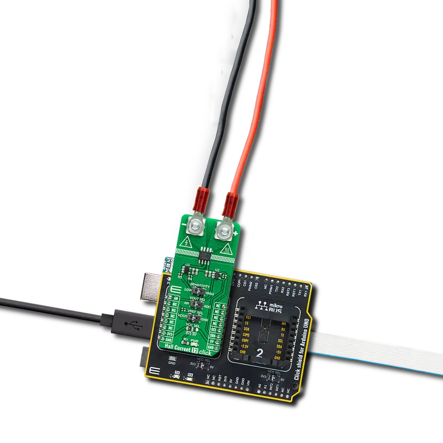
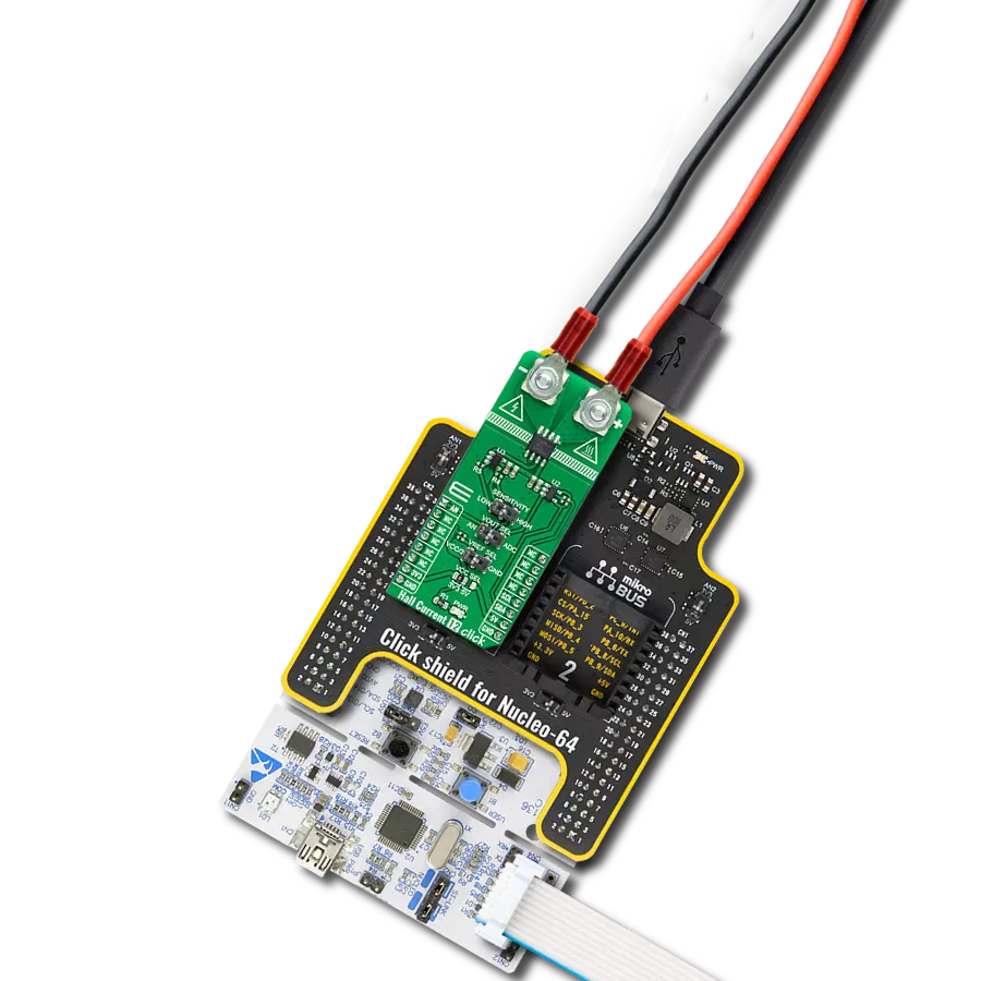
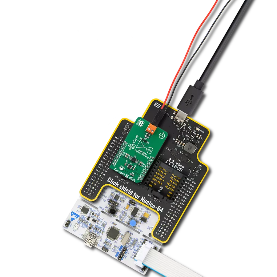
Start by selecting your development board and Click board™. Begin with the Fusion for Tiva v8 as your development board.


Track your results in real time
Application Output
1. Application Output - In Debug mode, the 'Application Output' window enables real-time data monitoring, offering direct insight into execution results. Ensure proper data display by configuring the environment correctly using the provided tutorial.

2. UART Terminal - Use the UART Terminal to monitor data transmission via a USB to UART converter, allowing direct communication between the Click board™ and your development system. Configure the baud rate and other serial settings according to your project's requirements to ensure proper functionality. For step-by-step setup instructions, refer to the provided tutorial.

3. Plot Output - The Plot feature offers a powerful way to visualize real-time sensor data, enabling trend analysis, debugging, and comparison of multiple data points. To set it up correctly, follow the provided tutorial, which includes a step-by-step example of using the Plot feature to display Click board™ readings. To use the Plot feature in your code, use the function: plot(*insert_graph_name*, variable_name);. This is a general format, and it is up to the user to replace 'insert_graph_name' with the actual graph name and 'variable_name' with the parameter to be displayed.

Software Support
Library Description
This library contains API for Hall Current Click driver.
Key functions:
hallcurrent_read_data- Generic read 16-bit data functionhallcurrent_check_status- Check status of read data functionhallcurrent_read_current- Read electric current function
Open Source
Code example
The complete application code and a ready-to-use project are available through the NECTO Studio Package Manager for direct installation in the NECTO Studio. The application code can also be found on the MIKROE GitHub account.
/*!
 * \file
 * \brief HallCurrent Click example
 *
 * # Description
 * The application is current sensor.
 *
 * The demo application is composed of two sections :
 *
 * ## Application Init
 * Initialization driver enable's - SPI and start write log.
 *
 * ## Application Task
 * This is an example which demonstrates the use of Hall Current Click board.
 *
 * \author MikroE Team
 *
 */
// ------------------------------------------------------------------- INCLUDES

#include "board.h"
#include "log.h"
#include "hallcurrent.h"

// ------------------------------------------------------------------ VARIABLES

static hallcurrent_t hallcurrent;
static log_t logger;

// ------------------------------------------------------ APPLICATION FUNCTIONS

void application_init ( void )
{
    log_cfg_t log_cfg;
    hallcurrent_cfg_t cfg;

    /**
     * Logger initialization.
     * Default baud rate: 115200
     * Default log level: LOG_LEVEL_DEBUG
     * @note If USB_UART_RX and USB_UART_TX
     * are defined as HAL_PIN_NC, you will
     * need to define them manually for log to work.
     * See @b LOG_MAP_USB_UART macro definition for detailed explanation.
     */
    LOG_MAP_USB_UART( log_cfg );
    log_init( &logger, &log_cfg );
    log_info( &logger, "---- Application Init ----" );

    //  Click initialization.
    hallcurrent_cfg_setup( &cfg );
    HALLCURRENT_MAP_MIKROBUS( cfg, MIKROBUS_1 );
    hallcurrent_init( &hallcurrent, &cfg );

    HALLCURRENT_SET_DATA_SAMPLE_EDGE;

    log_printf( &logger,"------------------------\r\n" );
    log_printf( &logger,  "       Hall Current     \r\n" );
    log_printf( &logger, "------------------------\r\n" );
}

void application_task ( void )
{
    log_printf( &logger, " Current : %.3f A \r\n", hallcurrent_read_current( &hallcurrent ) );
    log_printf( &logger, "------------------------\r\n" );
    Delay_ms ( 1000 );
}

int main ( void )
{
    /* Do not remove this line or clock might not be set correctly. */
    #ifdef PREINIT_SUPPORTED
    preinit();
    #endif

    application_init( );

    for ( ; ; )
    {
        application_task( );
    }

    return 0;
}


// ------------------------------------------------------------------------ END