Enhance magnetic field detection with TLI5012B-E1000 and STM32L496AG
Revolutionizing angle sensing with GMR technology
Published Jul 22, 2025
Click board™
GMR Angle Click
Dev. board
Discovery kit with STM32L496AG MCU
Compiler
NECTO Studio
MCU
STM32L496AG
Discover the transformative power of Giant Magneto Resistance (GMR) elements, enhancing precision in measuring magnetic field orientations.
A
A
Hardware Overview
How does it work?
GMR Angle Click is based on the TLI5012B E1000, a GMR-based 360° angle sensor from Infineon for detects any kind the orientation of a magnetic field, and the analog multiplexer 74HCT4053, switch a bi-directional Synchronous Serial Communication DATA line. This is achieved by measuring sine and cosine angle components with monolithic integrated Giant Magneto Resistance (iGMR) elements. These raw signals (sine and cosine) are digitally processed internally to calculate the angle orientation of the magnetic field (magnet). The calibration parameters are stored in laser fuses. At start-up the values of the fuses are written into flip-flops, where these values can be changed by the application-specific parameters. Further precision of the angle measurement over a wide temperature range and a long lifetime are improved with the internal autocalibration algorithm. The Giant Magneto Resistance (GMR) sensor is implemented using vertical integration. This means that the
GMR-sensitive areas are integrated above the logic part of the TLI5012B E1000 device. These GMR elements change their resistance depending on the direction of the magnetic field. Four individual GMR elements are connected to one Wheatstone sensor bridge. These GMR elements sense one of two components of the applied magnetic field: • X component, Vx (cosine) or the • Y component, Vy (sine) With this full-bridge structure the maximum GMR signal is available and temperature effects cancel out each other. The GMR Angle click also features the 74HCT4053, which is a triple single-pole double-throw analog switch (3x SPDT) suitable for use in analog or digital 2:1 multiplexer/demultiplexer applications. Each switch features a digital select input (Sn), two independent inputs/outputs (nY0 and nY1) and a common input/output (nZ). A digital enable input (E) is common to all switches. When E is HIGH, the switches are turned off. Inputs include clamp diodes. This enables the use of current limiting
resistors to interface inputs to voltages in excess of VCC. When CSS pin on microBUS is HIGH, switches in multiplexer connect DATA line with MOSI line, in other case when CSS pin is LOW, swithces connect DATA line with MISO line. The 74HCT4053 is mainly used for Analog multiplexing and demultiplexing, Digital multiplexing and demultiplexing and Signal gating, but in this one the 74HCT4053 is used for selection SPI line. These feature enable the GMR Angle click to be used for various applications, most notably for angular position sensing in industrial and consumer applications such as electrical commutated motor (e.g. BLDC), fans or pumps. This Click board™ can operate with either 3.3V or 5V logic voltage levels selected via the VCC SEL jumper. This way, both 3.3V and 5V capable MCUs can use the communication lines properly. This Click board™ comes equipped with a library containing easy-to-use functions and an example code that can be used as a reference for further development.


Features overview
Development board
The 32L496GDISCOVERY Discovery kit serves as a comprehensive demonstration and development platform for the STM32L496AG microcontroller, featuring an Arm® Cortex®-M4 core. Designed for applications that demand a balance of high performance, advanced graphics, and ultra-low power consumption, this kit enables seamless prototyping for a wide range of embedded solutions. With its innovative energy-efficient
architecture, the STM32L496AG integrates extended RAM and the Chrom-ART Accelerator, enhancing graphics performance while maintaining low power consumption. This makes the kit particularly well-suited for applications involving audio processing, graphical user interfaces, and real-time data acquisition, where energy efficiency is a key requirement. For ease of development, the board includes an onboard ST-LINK/V2-1
debugger/programmer, providing a seamless out-of-the-box experience for loading, debugging, and testing applications without requiring additional hardware. The combination of low power features, enhanced memory capabilities, and built-in debugging tools makes the 32L496GDISCOVERY kit an ideal choice for prototyping advanced embedded systems with state-of-the-art energy efficiency.

Microcontroller Overview
MCU Card / MCU

Architecture
ARM Cortex-M4
MCU Memory (KB)
1024
Silicon Vendor
STMicroelectronics
Pin count
169
RAM (Bytes)
327680
Used MCU Pins
mikroBUS™ mapper
Take a closer look
Click board™ Schematic

Step by step
Project assembly

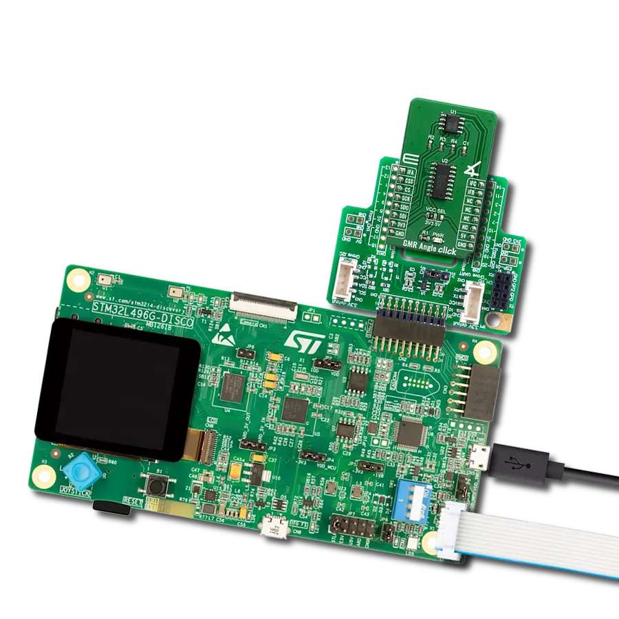
Start by selecting your development board and Click board™. Begin with the Discovery kit with STM32L496AG MCU as your development board.


Track your results in real time
Application Output
1. Application Output - In Debug mode, the 'Application Output' window enables real-time data monitoring, offering direct insight into execution results. Ensure proper data display by configuring the environment correctly using the provided tutorial.

2. UART Terminal - Use the UART Terminal to monitor data transmission via a USB to UART converter, allowing direct communication between the Click board™ and your development system. Configure the baud rate and other serial settings according to your project's requirements to ensure proper functionality. For step-by-step setup instructions, refer to the provided tutorial.

3. Plot Output - The Plot feature offers a powerful way to visualize real-time sensor data, enabling trend analysis, debugging, and comparison of multiple data points. To set it up correctly, follow the provided tutorial, which includes a step-by-step example of using the Plot feature to display Click board™ readings. To use the Plot feature in your code, use the function: plot(*insert_graph_name*, variable_name);. This is a general format, and it is up to the user to replace 'insert_graph_name' with the actual graph name and 'variable_name' with the parameter to be displayed.

Software Support
Library Description
This library contains API for GMR Angle Click driver.
Key functions:
gmrangle_read_data- Generic read 16-bit data functiongmrangle_write_data- Generic write 16-bit data functiongmrangle_calculate_angle- Calculate angle function.
Open Source
Code example
The complete application code and a ready-to-use project are available through the NECTO Studio Package Manager for direct installation in the NECTO Studio. The application code can also be found on the MIKROE GitHub account.
/*!
 * \file
 * \brief GmrAngle Click example
 *
 * # Description
 * This is an example which demonstrates the use of GMR Angle Click board.
 *
 * The demo application is composed of two sections :
 *
 * ## Application Init
 * Initializes GPIO pins, SPI and LOG modules.
 *
 * ## Application Task
 * Display angle value in degrees.
 * Results are being sent to the Usart Terminal where you can track their changes.
 * All data logs write on USB uart changes for every 300 msec.
 *
 * \author MikroE Team
 *
 */
// ------------------------------------------------------------------- INCLUDES

#include "board.h"
#include "log.h"
#include "gmrangle.h"

// ------------------------------------------------------------------ VARIABLES

static gmrangle_t gmrangle;
static log_t logger;
static float angle;

// ------------------------------------------------------ APPLICATION FUNCTIONS

void application_init ( void )
{
    log_cfg_t log_cfg;
    gmrangle_cfg_t cfg;

    /**
     * Logger initialization.
     * Default baud rate: 115200
     * Default log level: LOG_LEVEL_DEBUG
     * @note If USB_UART_RX and USB_UART_TX
     * are defined as HAL_PIN_NC, you will
     * need to define them manually for log to work.
     * See @b LOG_MAP_USB_UART macro definition for detailed explanation.
     */
    LOG_MAP_USB_UART( log_cfg );
    log_init( &logger, &log_cfg );
    log_info( &logger, "---- Application Init ----" );

    //  Click initialization.
    gmrangle_cfg_setup( &cfg );
    GMRANGLE_MAP_MIKROBUS( cfg, MIKROBUS_1 );
    gmrangle_init( &gmrangle, &cfg );

    GMRANGLE_SET_DATA_SAMPLE_EDGE;

    log_printf( &logger, "---------------------\r\n" );
    log_printf( &logger, "   GMR Angle Click\r\n" );
    log_printf( &logger, "---------------------\r\n" );
    log_printf( &logger, "        Start\r\n" );
    log_printf( &logger, "---------------------\r\n" );
    Delay_ms ( 100 );
}

void application_task ( void )
{
    angle = gmrangle_calculate_angle( &gmrangle );
    log_printf( &logger, " Angle is %.1f\r\n", angle );
    Delay_ms ( 300 );
}

int main ( void )
{
    /* Do not remove this line or clock might not be set correctly. */
    #ifdef PREINIT_SUPPORTED
    preinit();
    #endif

    application_init( );

    for ( ; ; )
    {
        application_task( );
    }

    return 0;
}


// ------------------------------------------------------------------------ END
Additional Support
Resources
Category:Magnetic