Create smarter, safer, and more connected environments with VCNL36825T and STM32F302VC
Revitalize your world with proximity awareness
Published Jul 22, 2025
Click board™
Proximity 14 Click
Dev. board
CLICKER 4 for STM32F302VCT6
Compiler
NECTO Studio
MCU
STM32F302VC
Discover how proximity detection goes beyond convenience, enabling you to effortlessly navigate your digital and physical worlds
A
A
Hardware Overview
How does it work?
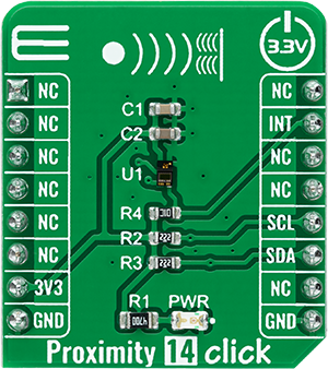
Proximity 14 Click is based on the VCNL36825T, a new fully integrated proximity sensor designed to increase efficiency and performance in consumer and industrial applications from Vishay Semiconductors. Featuring a vertical-cavity surface-emitting laser (VCSEL), the VCNL36825T combines a photodiode, signal processing IC, and 12-bit ADC in a compact SMD package with a small 1.6mm light hole. With a range of 20cm, it also provides collision detection and features low power consumption down to 6.63µA to increase efficiency in these applications. The VCNL36825T simplifies the use and design of a proximity sensor,
as no mechanical barriers are required to isolate the emitter from the detector optically. The proximity sensor uses intelligent cancellation to eliminate cross-talk, while a smart persistence scheme ensures accurate sensing and faster response time. The VCSEL wavelength peaks at 940nm and has no visible “red tail”. Proximity 14 Click communicates with MCU using the standard I2C 2-Wire interface to read data and configure settings, supporting Standard Mode operation with a clock frequency up to 100kHz and Fast Mode up to 400kHz. It also features an intelligent interrupt function that enables the sensor to work
independently until a predefined proximity event or threshold occurs. It then sets an interrupt that requires the MCU to awaken, which reduces power consumption by eliminating polling communication traffic between the sensor and the MCU. This Click board™ can be operated only with a 3.3V logic voltage level. The board must perform appropriate logic voltage level conversion before using MCUs with different logic levels. Also, it comes equipped with a library containing functions and an example code that can be used as a reference for further development.


Features overview
Development board
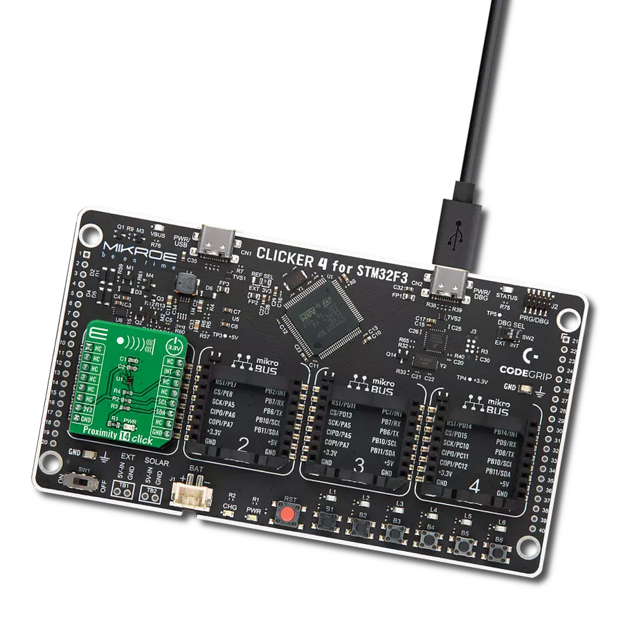
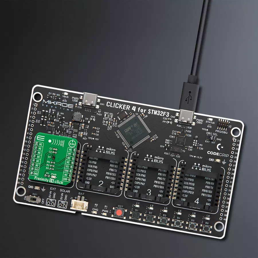
Clicker 4 for STM32F3 is a compact development board designed as a complete solution, you can use it to quickly build your own gadgets with unique functionalities. Featuring a STM32F302VCT6, four mikroBUS™ sockets for Click boards™ connectivity, power managment, and more, it represents a perfect solution for the rapid development of many different types of applications. At its core, there is a STM32F302VCT6 MCU, a powerful microcontroller by STMicroelectronics, based on the high-
performance Arm® Cortex®-M4 32-bit processor core operating at up to 168 MHz frequency. It provides sufficient processing power for the most demanding tasks, allowing Clicker 4 to adapt to any specific application requirements. Besides two 1x20 pin headers, four improved mikroBUS™ sockets represent the most distinctive connectivity feature, allowing access to a huge base of Click boards™, growing on a daily basis. Each section of Clicker 4 is clearly marked, offering an intuitive and clean interface. This makes working with the development
board much simpler and thus, faster. The usability of Clicker 4 doesn’t end with its ability to accelerate the prototyping and application development stages: it is designed as a complete solution which can be implemented directly into any project, with no additional hardware modifications required. Four mounting holes [4.2mm/0.165”] at all four corners allow simple installation by using mounting screws. For most applications, a nice stylish casing is all that is needed to turn the Clicker 4 development board into a fully functional, custom design.

Microcontroller Overview
MCU Card / MCU

Architecture
ARM Cortex-M4
MCU Memory (KB)
256
Silicon Vendor
STMicroelectronics
Pin count
100
RAM (Bytes)
40960
Used MCU Pins
mikroBUS™ mapper
Take a closer look
Click board™ Schematic

Step by step
Project assembly

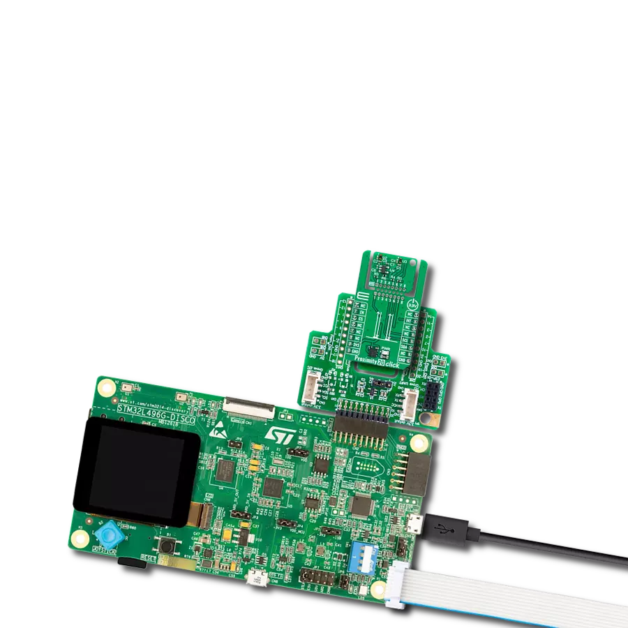
Start by selecting your development board and Click board™. Begin with the CLICKER 4 for STM32F302VCT6 as your development board.


Track your results in real time
Application Output
1. Application Output - In Debug mode, the 'Application Output' window enables real-time data monitoring, offering direct insight into execution results. Ensure proper data display by configuring the environment correctly using the provided tutorial.

2. UART Terminal - Use the UART Terminal to monitor data transmission via a USB to UART converter, allowing direct communication between the Click board™ and your development system. Configure the baud rate and other serial settings according to your project's requirements to ensure proper functionality. For step-by-step setup instructions, refer to the provided tutorial.

3. Plot Output - The Plot feature offers a powerful way to visualize real-time sensor data, enabling trend analysis, debugging, and comparison of multiple data points. To set it up correctly, follow the provided tutorial, which includes a step-by-step example of using the Plot feature to display Click board™ readings. To use the Plot feature in your code, use the function: plot(*insert_graph_name*, variable_name);. This is a general format, and it is up to the user to replace 'insert_graph_name' with the actual graph name and 'variable_name' with the parameter to be displayed.

Software Support
Library Description
This library contains API for Proximity 14 Click driver.
Key functions:
proximity14_generic_write- Writing functionproximity14_generic_read- Reading functionproximity14_get_int- Get INT pin state
Open Source
Code example
The complete application code and a ready-to-use project are available through the NECTO Studio Package Manager for direct installation in the NECTO Studio. The application code can also be found on the MIKROE GitHub account.
/*!
 * @file main.c
 * @brief Proximity14 Click example
 *
 * # Description
 * This example showcases the ability of the device to read proximity
 * value. It can be configured to detect objects up to 20cm of distance.
 *
 * The demo application is composed of two sections :
 *
 * ## Application Init
 * Initialization of host communication modules (UART, I2C) and
 * additional pins. Reads device ID and sets default configuration.
 *
 * ## Application Task
 * In span of 100ms reads proximity data from device and logs result.
 *
 * @author Luka Filipovic
 *
 */

#include "board.h"
#include "log.h"
#include "proximity14.h"

static proximity14_t proximity14;
static log_t logger;

void application_init ( void )
{
    log_cfg_t log_cfg;  /**< Logger config object. */
    proximity14_cfg_t proximity14_cfg;  /**< Click config object. */

    /**
     * Logger initialization.
     * Default baud rate: 115200
     * Default log level: LOG_LEVEL_DEBUG
     * @note If USB_UART_RX and USB_UART_TX
     * are defined as HAL_PIN_NC, you will
     * need to define them manually for log to work.
     * See @b LOG_MAP_USB_UART macro definition for detailed explanation.
     */
    LOG_MAP_USB_UART( log_cfg );
    log_init( &logger, &log_cfg );
    log_info( &logger, " Application Init " );

    // Click initialization.
    proximity14_cfg_setup( &proximity14_cfg );
    PROXIMITY14_MAP_MIKROBUS( proximity14_cfg, MIKROBUS_1 );
    err_t init_flag = proximity14_init( &proximity14, &proximity14_cfg );
    if ( I2C_MASTER_ERROR == init_flag )
    {
        log_error( &logger, " Application Init Error. " );
        log_info( &logger, " Please, run program again... " );

        for ( ; ; );
    }

    init_flag |= proximity14_default_cfg ( &proximity14 );
    if ( PROXIMITY14_OK != init_flag )
    {
        log_error( &logger, " Default configuration. " );
        log_info( &logger, " Please, run program again... " );

        for ( ; ; );
    }

    uint16_t temp_data = 0;
    init_flag = proximity14_generic_read( &proximity14, PROXIMITY14_REG_ID, &temp_data );
    log_printf( &logger, " > ID: 0x%.4X\r\n", temp_data );

    log_info( &logger, " Application Task " );
    Delay_ms ( 1000 );
}

void application_task ( void )
{
    uint16_t temp_data = 0;
    proximity14_generic_read( &proximity14, PROXIMITY14_REG_DATA, &temp_data );
    log_printf( &logger, " > Data: %u\r\n", temp_data );
    Delay_ms ( 100 );
}

int main ( void )
{
    /* Do not remove this line or clock might not be set correctly. */
    #ifdef PREINIT_SUPPORTED
    preinit();
    #endif

    application_init( );

    for ( ; ; )
    {
        application_task( );
    }

    return 0;
}

// ------------------------------------------------------------------------ END
Additional Support
Resources
Category:Proximity