Achieve precise timing and synchronization with DS1682 and ATmega1284
Countdown to excellence
Published Oct 20, 2023
Click board™
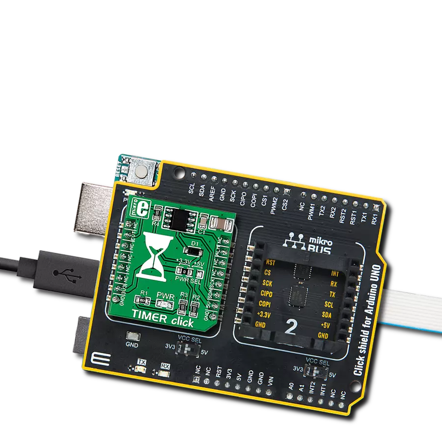
TIMER Click
Dev. board
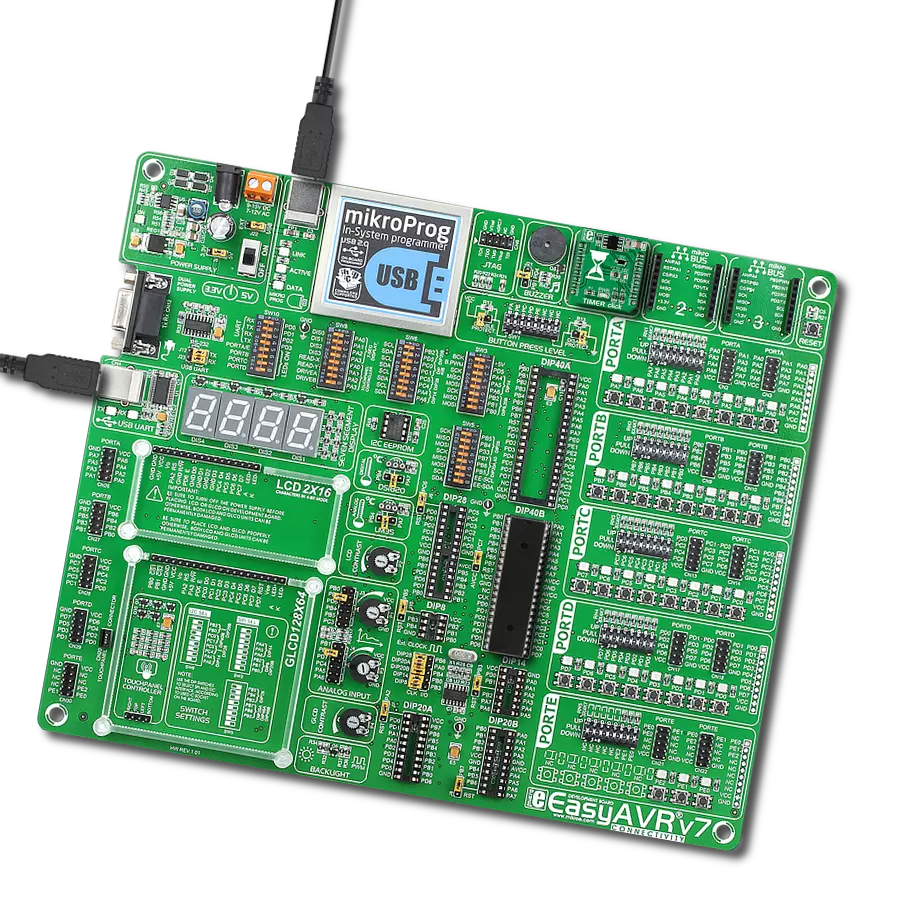
EasyAVR v7
Compiler
NECTO Studio
MCU
ATmega1284
Take control of your time with a powerful countdown timer
A
A
Hardware Overview
How does it work?
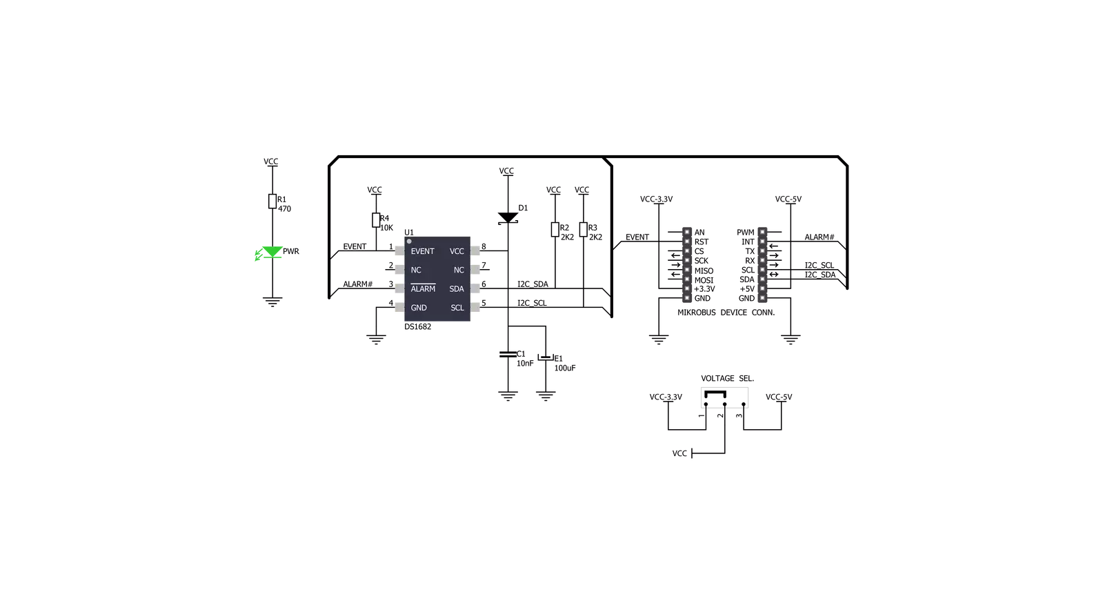
Timer Click is based on the DS1682, a total-elapsed-time recorder with an alarm from Analog Devices. This IC is an integrated ETC, factory-calibrated, and temperature-compensated RC time base, accurate to 2% (typical), eliminating the need for an external crystal. The DS1682 can detect and record the number of events and the total cumulative event time since the last reset to 0. After the Power-Up sequence, the data is transferred from the EEPROM into the counters and registers where data can be read and written. The data from the counters and registers are written to the EEPROM when the event occurs.
The Timer Click communicates with the host microcontroller using the standard I2C 2-Wire interface to read data and configure settings, supporting Standard mode (100KHz) and Fast mode (400KHz) operation. The event EVT pin is the input pin of the DS1682 and monitors when an event occurs. With logic HIGH on this pin, the contents from the EEPROM are transferred to the ETC, and the ETC counter starts to count in quarter-second increments. With logic LOW, event counter increments and the data are stored in the EEPROM array. When the EVT pin changes states, the I2C is unavailable for communications. The
ALM is an alarm output pin and is active LOW. When the ETC matches the alarm value, the alarm flag (AF) is set, and once set, it can not be reset. The alarm flag is one-time programmable. This Click board™ can operate with either 3.3V or 5V logic voltage levels selected via the PWR SEL jumper. This way, both 3.3V and 5V capable MCUs can use the communication lines properly. Also, this Click board™ comes equipped with a library containing easy-to-use functions and an example code that can be used as a reference for further development.


Features overview
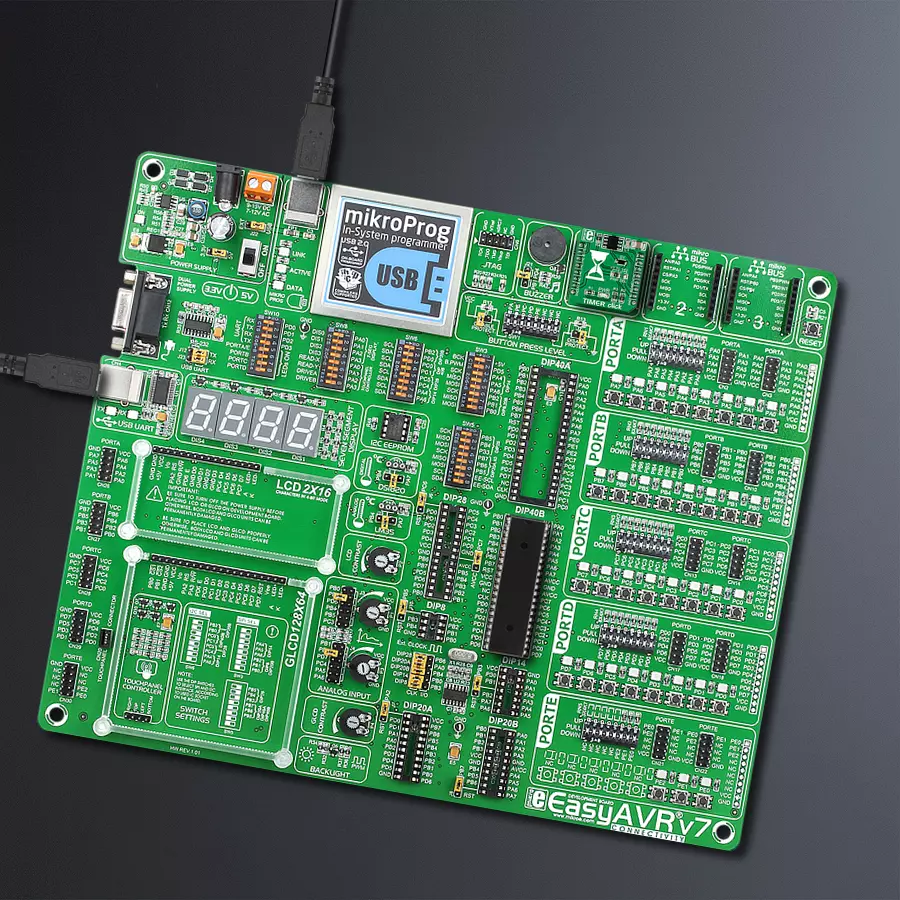
Development board
EasyAVR v7 is the seventh generation of AVR development boards specially designed for the needs of rapid development of embedded applications. It supports a wide range of 16-bit AVR microcontrollers from Microchip and has a broad set of unique functions, such as a powerful onboard mikroProg programmer and In-Circuit debugger over USB. The development board is well organized and designed so that the end-user has all the necessary elements in one place, such as switches, buttons, indicators, connectors, and others. With four different connectors for each port, EasyAVR v7 allows you to connect accessory boards, sensors, and custom electronics more
efficiently than ever. Each part of the EasyAVR v7 development board contains the components necessary for the most efficient operation of the same board. An integrated mikroProg, a fast USB 2.0 programmer with mikroICD hardware In-Circuit Debugger, offers many valuable programming/debugging options and seamless integration with the Mikroe software environment. Besides it also includes a clean and regulated power supply block for the development board. It can use a wide range of external power sources, including an external 12V power supply, 7-12V AC or 9-15V DC via DC connector/screw terminals, and a power source via the USB Type-B (USB-B)
connector. Communication options such as USB-UART and RS-232 are also included, alongside the well-established mikroBUS™ standard, three display options (7-segment, graphical, and character-based LCD), and several different DIP sockets which cover a wide range of 16-bit AVR MCUs. EasyAVR v7 is an integral part of the Mikroe ecosystem for rapid development. Natively supported by Mikroe software tools, it covers many aspects of prototyping and development thanks to a considerable number of different Click boards™ (over a thousand boards), the number of which is growing every day.

Microcontroller Overview
MCU Card / MCU

Architecture
AVR
MCU Memory (KB)
128
Silicon Vendor
Microchip
Pin count
40
RAM (Bytes)
16384
Used MCU Pins
mikroBUS™ mapper
Take a closer look
Click board™ Schematic
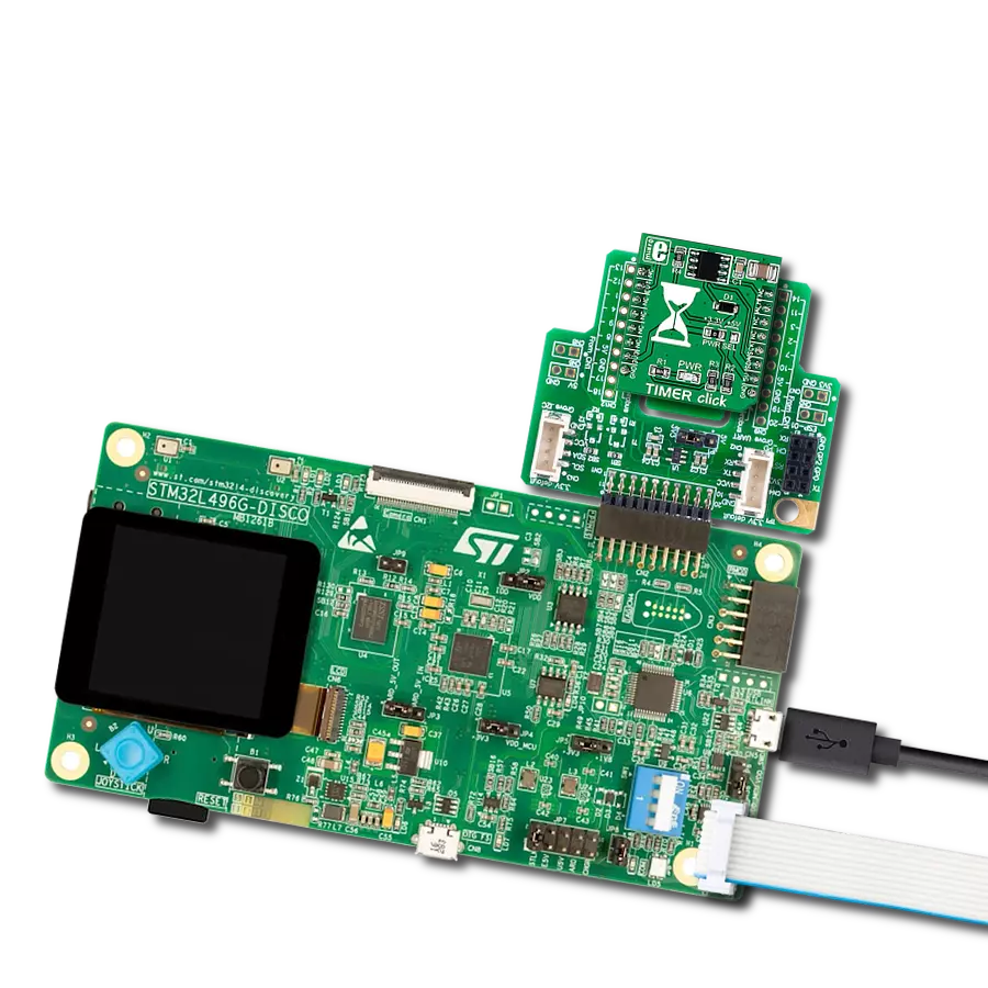
Step by step
Project assembly

Start by selecting your development board and Click board™. Begin with the EasyAVR v7 as your development board.


Track your results in real time
Application Output
1. Application Output - In Debug mode, the 'Application Output' window enables real-time data monitoring, offering direct insight into execution results. Ensure proper data display by configuring the environment correctly using the provided tutorial.

2. UART Terminal - Use the UART Terminal to monitor data transmission via a USB to UART converter, allowing direct communication between the Click board™ and your development system. Configure the baud rate and other serial settings according to your project's requirements to ensure proper functionality. For step-by-step setup instructions, refer to the provided tutorial.

3. Plot Output - The Plot feature offers a powerful way to visualize real-time sensor data, enabling trend analysis, debugging, and comparison of multiple data points. To set it up correctly, follow the provided tutorial, which includes a step-by-step example of using the Plot feature to display Click board™ readings. To use the Plot feature in your code, use the function: plot(*insert_graph_name*, variable_name);. This is a general format, and it is up to the user to replace 'insert_graph_name' with the actual graph name and 'variable_name' with the parameter to be displayed.

Software Support
Library Description
This library contains API for TIMER Click driver.
Key functions:
timer_get_etc_data- Get elapsed time counter (ETC) data functiontimer_get_etc_seconds- Get elapsed time counter (ETC) seconds functiontimer_get_time- Set elapsed time counter (ETC) time function
Open Source
Code example
The complete application code and a ready-to-use project are available through the NECTO Studio Package Manager for direct installation in the NECTO Studio. The application code can also be found on the MIKROE GitHub account.
/*!
 * \file
 * \brief Timer Click example
 *
 * # Description
 * This application is multifunctional 3-axis digital accelerometer that can also be configured as a 45-degree Tilt sensor.
 *
 * The demo application is composed of two sections :
 *
 * ## Application Init
 * Initialization driver enable's - I2C,
 * soft reset, sets ETC and EC start ( seconds ), hardwere reset and start write log.
 *
 * ## Application Task
 * This is a example which demonstrates the use of Timer Click board.
 * Timer Click communicates with register via I2C by write to register and read from register,
 * display time ( days, hours, minutes and seconds ) which we received reading from the target register address of DS1682 total elapsed time recorder.
 * Results are being sent to the Usart Terminal where you can track their changes.
 * All data logs write on usb uart changes for every 1 sec.
 *
 * \author MikroE Team
 *
 */
// ------------------------------------------------------------------- INCLUDES

#include "board.h"
#include "log.h"
#include "timer.h"

// ------------------------------------------------------------------ VARIABLES

static timer_t timer;
static log_t logger;
static uint8_t time_seconds_new;

// ------------------------------------------------------ APPLICATION FUNCTIONS

void application_init ( void )
{
    log_cfg_t log_cfg;
    timer_cfg_t cfg;

    /**
     * Logger initialization.
     * Default baud rate: 115200
     * Default log level: LOG_LEVEL_DEBUG
     * @note If USB_UART_RX and USB_UART_TX
     * are defined as HAL_PIN_NC, you will
     * need to define them manually for log to work.
     * See @b LOG_MAP_USB_UART macro definition for detailed explanation.
     */
    LOG_MAP_USB_UART( log_cfg );
    log_init( &logger, &log_cfg );
    log_info( &logger, "---- Application Init ----" );

    //  Click initialization.

    timer_cfg_setup( &cfg );
    TIMER_MAP_MIKROBUS( cfg, MIKROBUS_1 );
    timer_init( &timer, &cfg );
    Delay_ms ( 200 );

    log_printf( &logger, "   Driver  Init   \r\n" );
    log_printf( &logger, "------------------\r\n" );
    log_printf( &logger, "    Soft Reset    \r\n" );

    timer_soft_reset( &timer );
    Delay_ms ( 500 );

    log_printf( &logger, "------------------\r\n" );
    log_printf( &logger, "  Set ETC and EC  \r\n" );

    timer_set_etc_seconds( &timer, 86390 );
    timer_set_ec_seconds( &timer, 0 );

    log_printf( &logger, "------------------\r\n" );
    log_printf( &logger, "  Hardwere Reset  \r\n" );

    timer_hw_reset( &timer );
    Delay_ms ( 500 );

    log_printf( &logger, "------------------\r\n" );
    log_printf( &logger, "        ETC       \r\n" );
    log_printf( &logger, "------------------\r\n" );

    time_seconds_new = 0xFF;
}

void application_task ( )
{
    uint8_t time_hours;
    uint8_t time_minutes;
    uint8_t time_seconds;
    uint16_t time_days;

    timer_get_time( &timer, &time_days, &time_hours, &time_minutes, &time_seconds );

    if ( time_seconds_new != time_seconds )
    {
        log_printf
        (
            &logger, " %d days    %d:%d:%d \r\n",
            (uint16_t)time_days,
            (uint16_t)time_hours,
            (uint16_t)time_minutes,
            (uint16_t)time_seconds
        );
        log_printf( &logger, "------------------\r\n" );
        time_seconds_new = time_seconds;
    }
    Delay_ms ( 1 );
}

int main ( void )
{
    /* Do not remove this line or clock might not be set correctly. */
    #ifdef PREINIT_SUPPORTED
    preinit();
    #endif

    application_init( );

    for ( ; ; )
    {
        application_task( );
    }

    return 0;
}


// ------------------------------------------------------------------------ END