Extend the lifetime and current capability of a battery cells with NBM5100A and ATmega1284P
Battery life booster with adaptive power optimization

Published Feb 12, 2024
Click board™
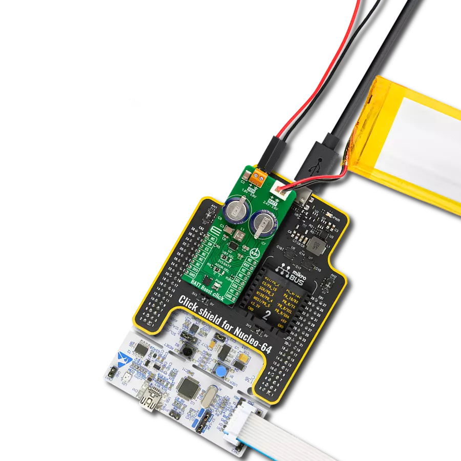
BATT Boost Click
Dev. board
EasyAVR v7
Compiler
NECTO Studio
MCU
ATmega1284P
Enhance the power and prolong the lifespan of coin battery cells like the CR2032, ensuring longer-lasting performance for a wide range of electronic devices
A
A
Hardware Overview
How does it work?
BATT Boost Click is based on the NBM5100A, a coin-cell battery life booster with adaptive power optimization from Nexperia. It contains an intelligent learning algorithm and two stages of high-efficiency DC-DC conversion. The first stage, DC-DC conversion, transfers energy from the lithium battery to a capacitive storage element at a low constant current. When charged, a second DC-DC conversion cycle utilizes this stored energy to supply a regulated voltage with high pulse load current capability on the VDH output terminal. The battery is never directly subjected to large load pulse currents, resulting in a longer, more predictable battery lifetime. The NBM5100A has a programmable constant battery load current of 2mA
up to 16mA. It also features an ultra-low standby current, integrated fuel gauge, high peak power efficiency, low pulse output current, protection against battery voltage dips, and more. The capacitor balancing IO of the NBM1500A is connected to two supercapacitors and is intended for applications utilizing series-connected supercapacitors requiring voltage balancing. The input supply source of the NBM5100A can be selected from the 3.3V rail of the mikroBUS™ socket or the coin battery itself. The selection can be made over the VBT SEL jumper. BATT Boost Click uses a standard 2-wire I2C interface to communicate with the host MCU, supporting a clock frequency of up to 1MHz. The I2C address
can be selected over the ADDR SEL jumper. The auto mode utilizes the start pin (ON) for one cycle. There are two ways to define the end of the active state in auto mode: short pulse on the ON pin and long pulse on the ON pin. The NBM1500A will interrupt the host MCU when it is ready over the RDY pin. This Click board™ can be operated only with a 3.3V logic voltage level. The board must perform appropriate logic voltage level conversion before using MCUs with different logic levels. Also, it comes equipped with a library containing functions and an example code that can be used as a reference for further development.

Features overview
Development board
EasyAVR v7 is the seventh generation of AVR development boards specially designed for the needs of rapid development of embedded applications. It supports a wide range of 16-bit AVR microcontrollers from Microchip and has a broad set of unique functions, such as a powerful onboard mikroProg programmer and In-Circuit debugger over USB. The development board is well organized and designed so that the end-user has all the necessary elements in one place, such as switches, buttons, indicators, connectors, and others. With four different connectors for each port, EasyAVR v7 allows you to connect accessory boards, sensors, and custom electronics more
efficiently than ever. Each part of the EasyAVR v7 development board contains the components necessary for the most efficient operation of the same board. An integrated mikroProg, a fast USB 2.0 programmer with mikroICD hardware In-Circuit Debugger, offers many valuable programming/debugging options and seamless integration with the Mikroe software environment. Besides it also includes a clean and regulated power supply block for the development board. It can use a wide range of external power sources, including an external 12V power supply, 7-12V AC or 9-15V DC via DC connector/screw terminals, and a power source via the USB Type-B (USB-B)
connector. Communication options such as USB-UART and RS-232 are also included, alongside the well-established mikroBUS™ standard, three display options (7-segment, graphical, and character-based LCD), and several different DIP sockets which cover a wide range of 16-bit AVR MCUs. EasyAVR v7 is an integral part of the Mikroe ecosystem for rapid development. Natively supported by Mikroe software tools, it covers many aspects of prototyping and development thanks to a considerable number of different Click boards™ (over a thousand boards), the number of which is growing every day.

Microcontroller Overview
MCU Card / MCU
Architecture
AVR
MCU Memory (KB)
128
Silicon Vendor
Microchip
Pin count
40
RAM (Bytes)
16384
You complete me!
Accessories
Li-Polymer Battery is the ideal solution for devices that demand a dependable and long-lasting power supply while emphasizing mobility. Its compatibility with mikromedia boards ensures easy integration without additional modifications. With a voltage output of 3.7V, the battery meets the standard requirements of many electronic devices. Additionally, boasting a capacity of 2000mAh, it can store a substantial amount of energy, providing sustained power for extended periods. This feature minimizes the need for frequent recharging or replacement. Overall, the Li-Polymer Battery is a reliable and autonomous power source, ideally suited for devices requiring a stable and enduring energy solution. You can find a more extensive choice of Li-Polymer batteries in our offer.

Used MCU Pins
mikroBUS™ mapper
Take a closer look
Click board™ Schematic

Step by step
Project assembly

Start by selecting your development board and Click board™. Begin with the EasyAVR v7 as your development board.


Track your results in real time
Application Output
1. Application Output - In Debug mode, the 'Application Output' window enables real-time data monitoring, offering direct insight into execution results. Ensure proper data display by configuring the environment correctly using the provided tutorial.

2. UART Terminal - Use the UART Terminal to monitor data transmission via a USB to UART converter, allowing direct communication between the Click board™ and your development system. Configure the baud rate and other serial settings according to your project's requirements to ensure proper functionality. For step-by-step setup instructions, refer to the provided tutorial.

3. Plot Output - The Plot feature offers a powerful way to visualize real-time sensor data, enabling trend analysis, debugging, and comparison of multiple data points. To set it up correctly, follow the provided tutorial, which includes a step-by-step example of using the Plot feature to display Click board™ readings. To use the Plot feature in your code, use the function: plot(*insert_graph_name*, variable_name);. This is a general format, and it is up to the user to replace 'insert_graph_name' with the actual graph name and 'variable_name' with the parameter to be displayed.

Software Support
Library Description
This library contains API for BATT Boost Click driver.
Key functions:
battboost_get_vcap- This function is used to read the storage capacitor voltage statusbattboost_set_op_mode- This function is used to select the desired operating mode of the devicebattboost_get_status- This function reads the the status information of low battery input, capacitor input voltage early warning, VDH output alarm and ready state
Open Source
Code example
The complete application code and a ready-to-use project are available through the NECTO Studio Package Manager for direct installation in the NECTO Studio. The application code can also be found on the MIKROE GitHub account.
/*!
 * @file main.c
 * @brief BATT Boost Click example
 *
 * # Description
 * This library contains API for the BATT Boost Click driver.
 * This driver provides the functions to controle battery energy management
 * device designed to maximize usable capacity from non-rechargeable.
 *
 * The demo application is composed of two sections :
 *
 * ## Application Init
 * Initialization of I2C module and log UART.
 * After driver initialization, the app executes a default configuration,
 * sets the output voltage to 1.8V, charge current to 16mA,
 * and early warning voltage to 2.6V.
 *
 * ## Application Task
 * This example demonstrates the use of the BATT Boost Click board.
 * The demo application uses two operations in two states:
 * the charging state and the active state. First, when the device is in a Charge state,
 * the external storage capacitor is charging from VBT using a constant current
 * and displays storage capacitor voltage levels and charge cycle count.
 * Upon completion of a Charge state, the device transitions to the Active state
 * at which time VDH becomes a regulated voltage output of 1.8V (default configuration),
 * displays storage capacitor voltage level, and monitors alarms
 * for low output voltage (below 1.8V) and early warning (below 2.4V).
 * Results are being sent to the UART Terminal, where you can track their changes.
 *
 * @author Nenad Filipovic
 *
 */

#include "board.h"
#include "log.h"
#include "battboost.h"

static battboost_t battboost;
static log_t logger;

void application_init ( void )
{
    log_cfg_t log_cfg;  /**< Logger config object. */
    battboost_cfg_t battboost_cfg;  /**< Click config object. */

    /**
     * Logger initialization.
     * Default baud rate: 115200
     * Default log level: LOG_LEVEL_DEBUG
     * @note If USB_UART_RX and USB_UART_TX
     * are defined as HAL_PIN_NC, you will
     * need to define them manually for log to work.
     * See @b LOG_MAP_USB_UART macro definition for detailed explanation.
     */
    LOG_MAP_USB_UART( log_cfg );
    log_init( &logger, &log_cfg );
    log_info( &logger, " Application Init " );

    // Click initialization.
    battboost_cfg_setup( &battboost_cfg );
    BATTBOOST_MAP_MIKROBUS( battboost_cfg, MIKROBUS_1 );
    if ( I2C_MASTER_ERROR == battboost_init( &battboost, &battboost_cfg ) )
    {
        log_error( &logger, " Communication init." );
        for ( ; ; );
    }

    if ( BATTBOOST_ERROR == battboost_default_cfg ( &battboost ) )
    {
        log_error( &logger, " Default configuration." );
        for ( ; ; );
    }

    log_info( &logger, " Application Task " );
    Delay_ms ( 100 );
}

void application_task ( void )
{
    float vcap = 0;
    uint8_t status = 0;
    uint32_t chenergy = 0;

    if ( BATTBOOST_STATUS_READY != battboost_get_ready( &battboost ) )
    {
        if ( BATTBOOST_OK == battboost_set_op_mode( &battboost, BATTBOOST_OP_MODE_CHARGE ) )
        {
            log_printf( &logger, "\nOperating state: Charge\r\n" );
        }

        if ( BATTBOOST_OK == battboost_get_vcap( &battboost, &vcap ) )
        {
            log_printf( &logger, " Capacitor Voltage: %.2f V \r\n", vcap );
        }

        if ( BATTBOOST_OK == battboost_get_chenergy( &battboost, &chenergy ) )
        {
            log_printf( &logger, " Charge cycle count: %lu \r\n", chenergy );
        }
        Delay_ms ( 1000 );
    }
    else
    {
        if ( BATTBOOST_OK == battboost_set_op_mode( &battboost, BATTBOOST_OP_MODE_ACTIVE ) )
        {
            log_printf( &logger, "\nOperating state: Active\r\n" );
            if ( BATTBOOST_OK == battboost_get_vcap( &battboost, &vcap ) )
            {
                log_printf( &logger, " Capacitor Voltage: %.2f V \r\n", vcap );
            }

            if ( BATTBOOST_OK == battboost_get_status( &battboost, &status ) )
            {
                if ( BATTBOOST_STATUS_EW & status )
                {
                    log_printf( &logger, " Status: Early warning.\r\n" );
                }

                if ( BATTBOOST_STATUS_ALRM & status )
                {
                    log_printf( &logger, " Status: Low output voltage in the Active state.\r\n" );
                }
            }
        }
        Delay_ms ( 1000 );
    }
}

int main ( void )
{
    /* Do not remove this line or clock might not be set correctly. */
    #ifdef PREINIT_SUPPORTED
    preinit();
    #endif

    application_init( );

    for ( ; ; )
    {
        application_task( );
    }

    return 0;
}

// ------------------------------------------------------------------------ END