Ignite your power with TPS55332-Q1 and STM32F446RE
Experience the boost

Published Oct 08, 2024
Click board™
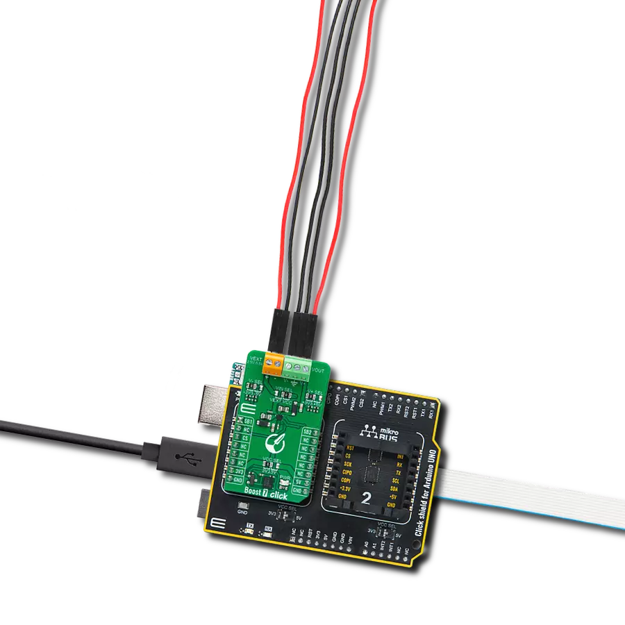
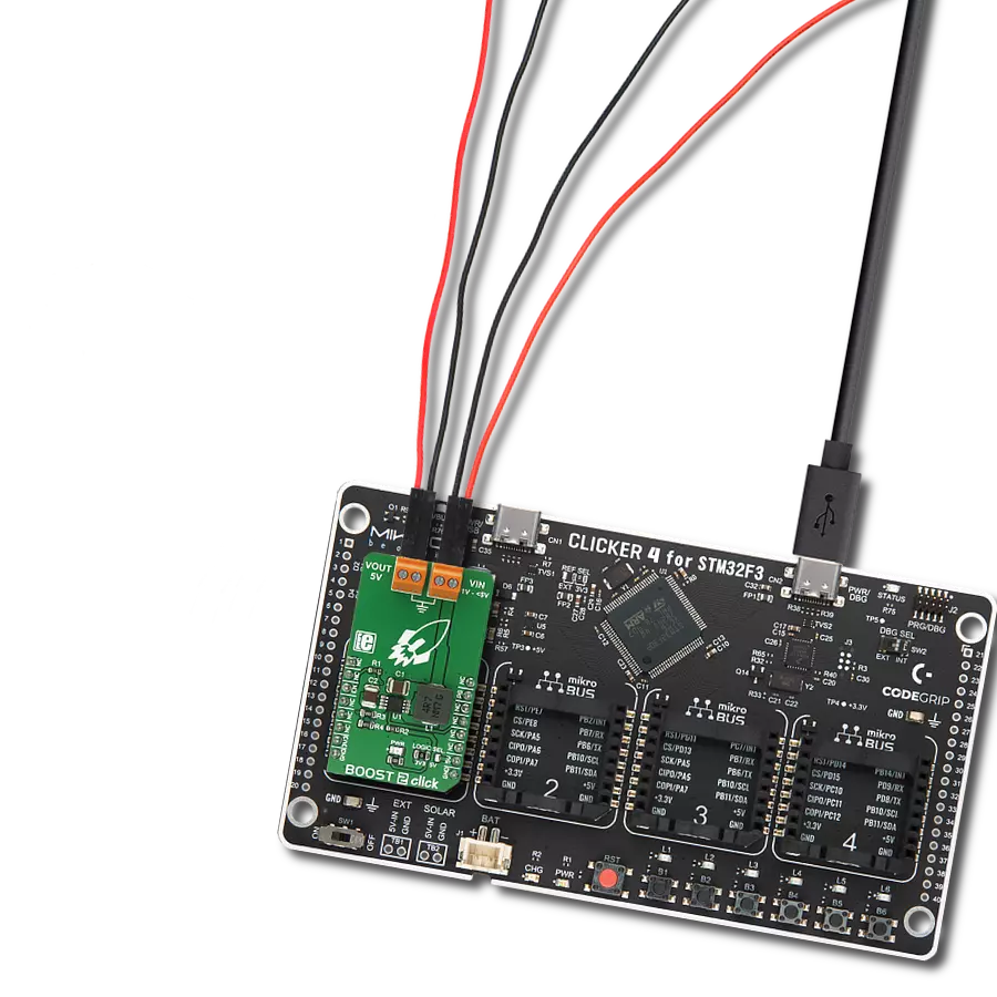
Boost 6 Click
Dev. board
Nucleo 64 with STM32F446RE MCU
Compiler
NECTO Studio
MCU
STM32F446RE
Empower your circuits to soar with our state-of-the-art voltage booster!
A
A
Hardware Overview
How does it work?
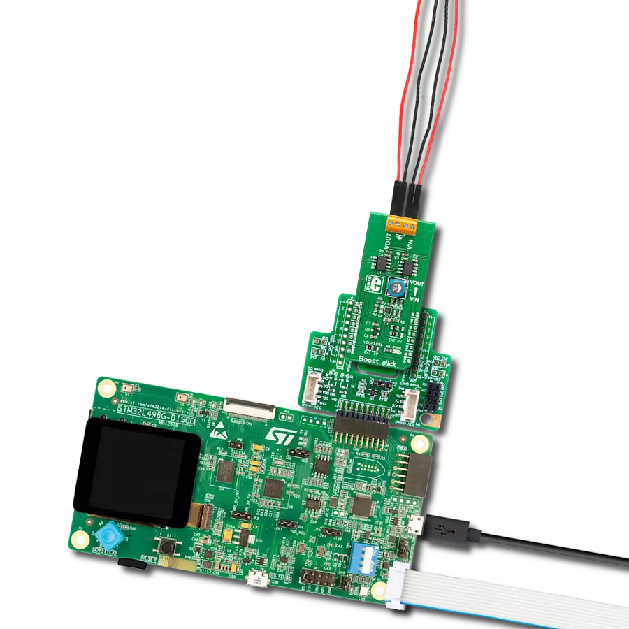
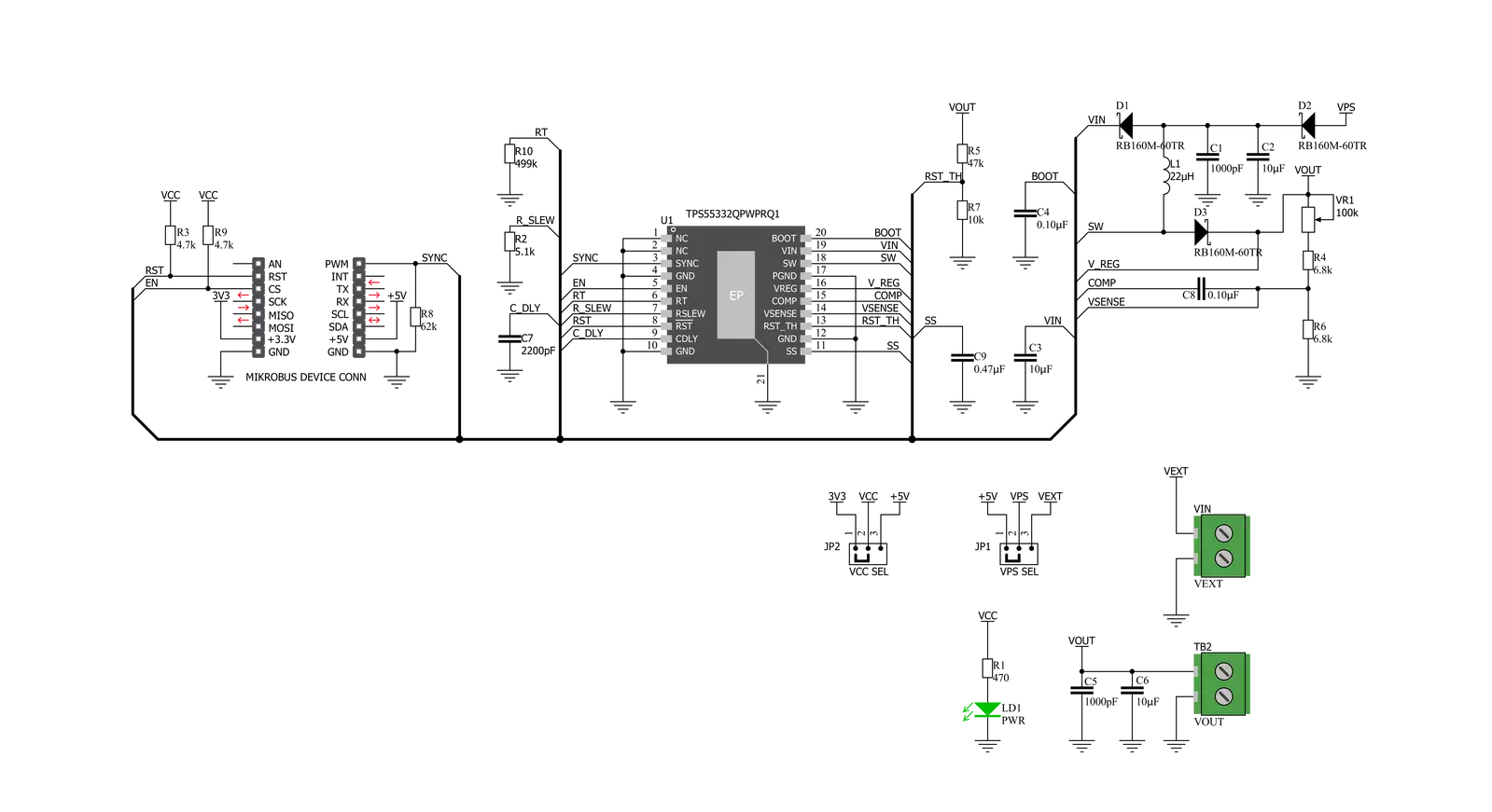
Boost 6 Click is based on the TPS55332-Q1, the monolithic high-voltage switching regulator from Texas Instruments. It is important to state that it operates as a step-up (boost) converter. The feedback concept is voltage mode control using the VSENSE terminal with a cycle-by-cycle current limit. The voltage supervisory function for power-on-rest during system power-on monitoring the output voltage, and once this has exceeded the threshold set by RST_TH, a delay of 1.0 ms/nF (based on the capacitor value on the Cdly terminal) is invoked before the RST line is released high. The output is sensed through an external resistor divider and compared with an internal reference voltage. The value of the adjustable output voltage in boost mode is selectable between VIN × 1.05 to 50 V if the minimum ON time (ton) and minimum OFF times are NOT violated by choosing the external resistors. The internal reference voltage Vref has a ±1.5% tolerance. The potentiometer featured on the Boost 6 click can change the feedback, thus influencing a change in the output voltage.
This makes the Click extremely practical because you can get the full voltage range with a simple turn of the potentiometer. Once the internal circuits have stabilized with a minimum input supply of 3.6V, the system can have an input voltage range from 1.5V to 40V to maintain a fixed boost output voltage. Over-current protection is implemented by sensing the current through the NMOS switch FET. The sensed current is then compared to a current reference level representing the over-current threshold limit. The over-current indicator is set to true if the sensed current exceeds the over-current threshold limit. The system ignores the over-current indicator for the leading edge blanking time at the beginning of each cycle to avoid any turn-on noise glitches. The oscillator frequency is selectable by means of a resistor placed at the RT pin. The switching frequency (ƒsw) can be set at 80kHz to 2.2MHz. The power-on reset output is asserted low until the output voltage exceeds the programmed Vreg_RST voltage threshold and the reset delay timer has expired. Additionally, whenever the
Enable pin is low or open, RST is immediately asserted low regardless of the output voltage. There is a reset de-glitch timer to prevent a reset from being invoked due to short negative transients on the output line. The TPS55332-Q1 device is designed to operate from an input voltage of up to 40 V. Ensure that the input supply is well-regulated and can protect itself from overheating with an internal thermal shutdown circuit. The MOSFET is turned off if the junction temperature exceeds the thermal shutdown trip point. The device is restarted under the control of the slow start circuit automatically when the junction temperature drops below the thermal shutdown hysteresis trip point. This Click board™ can operate with either 3.3V or 5V logic voltage levels selected via the VCC SEL jumper. This way, both 3.3V and 5V capable MCUs can use the communication lines properly. However, the Click board™ comes equipped with a library containing easy-to-use functions and an example code that can be used, as a reference, for further development.

Features overview
Development board
Nucleo-64 with STM32F446RE MCU offers a cost-effective and adaptable platform for developers to explore new ideas and prototype their designs. This board harnesses the versatility of the STM32 microcontroller, enabling users to select the optimal balance of performance and power consumption for their projects. It accommodates the STM32 microcontroller in the LQFP64 package and includes essential components such as a user LED, which doubles as an ARDUINO® signal, alongside user and reset push-buttons, and a 32.768kHz crystal oscillator for precise timing operations. Designed with expansion and flexibility in mind, the Nucleo-64 board features an ARDUINO® Uno V3 expansion connector and ST morpho extension pin
headers, granting complete access to the STM32's I/Os for comprehensive project integration. Power supply options are adaptable, supporting ST-LINK USB VBUS or external power sources, ensuring adaptability in various development environments. The board also has an on-board ST-LINK debugger/programmer with USB re-enumeration capability, simplifying the programming and debugging process. Moreover, the board is designed to simplify advanced development with its external SMPS for efficient Vcore logic supply, support for USB Device full speed or USB SNK/UFP full speed, and built-in cryptographic features, enhancing both the power efficiency and security of projects. Additional connectivity is
provided through dedicated connectors for external SMPS experimentation, a USB connector for the ST-LINK, and a MIPI® debug connector, expanding the possibilities for hardware interfacing and experimentation. Developers will find extensive support through comprehensive free software libraries and examples, courtesy of the STM32Cube MCU Package. This, combined with compatibility with a wide array of Integrated Development Environments (IDEs), including IAR Embedded Workbench®, MDK-ARM, and STM32CubeIDE, ensures a smooth and efficient development experience, allowing users to fully leverage the capabilities of the Nucleo-64 board in their projects.

Microcontroller Overview
MCU Card / MCU

Architecture
ARM Cortex-M4
MCU Memory (KB)
512
Silicon Vendor
STMicroelectronics
Pin count
64
RAM (Bytes)
131072
You complete me!
Accessories
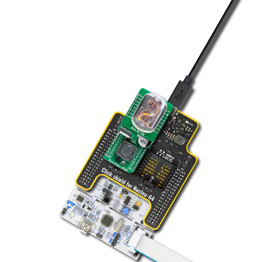
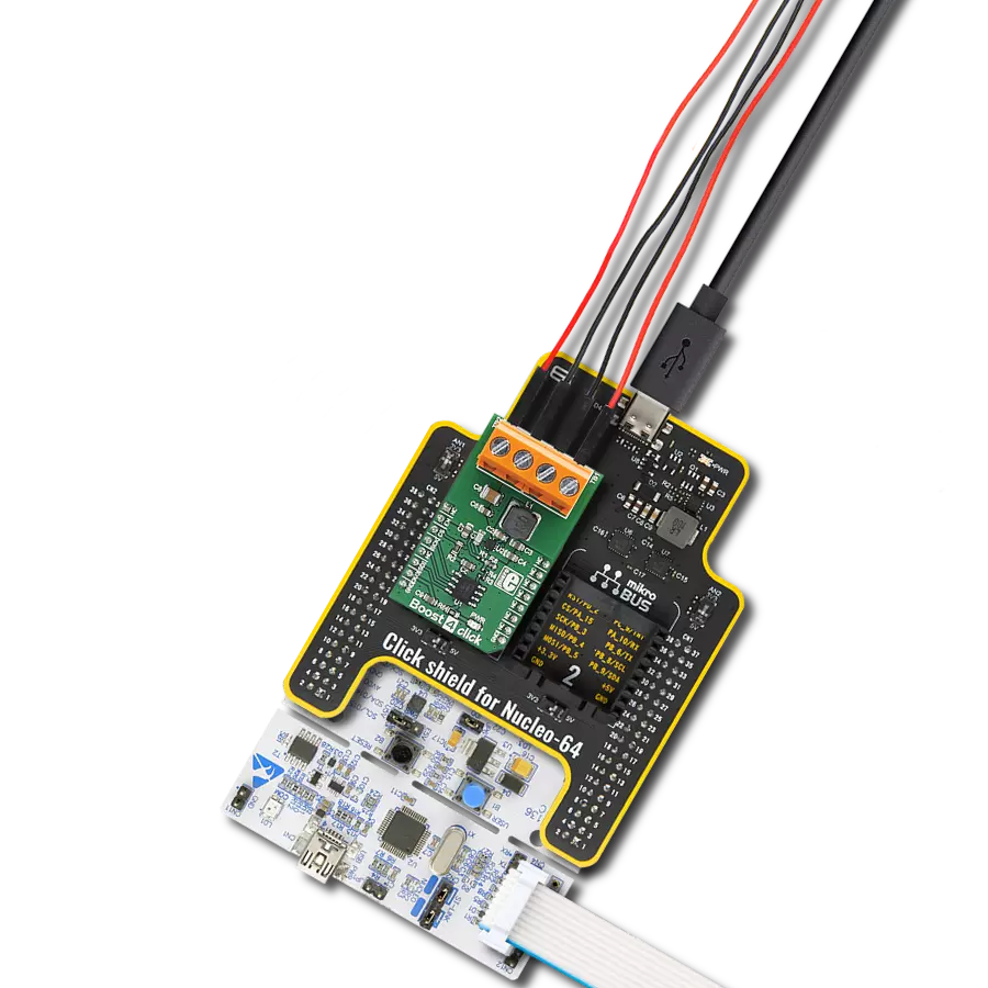
Click Shield for Nucleo-64 comes equipped with two proprietary mikroBUS™ sockets, allowing all the Click board™ devices to be interfaced with the STM32 Nucleo-64 board with no effort. This way, Mikroe allows its users to add any functionality from our ever-growing range of Click boards™, such as WiFi, GSM, GPS, Bluetooth, ZigBee, environmental sensors, LEDs, speech recognition, motor control, movement sensors, and many more. More than 1537 Click boards™, which can be stacked and integrated, are at your disposal. The STM32 Nucleo-64 boards are based on the microcontrollers in 64-pin packages, a 32-bit MCU with an ARM Cortex M4 processor operating at 84MHz, 512Kb Flash, and 96KB SRAM, divided into two regions where the top section represents the ST-Link/V2 debugger and programmer while the bottom section of the board is an actual development board. These boards are controlled and powered conveniently through a USB connection to program and efficiently debug the Nucleo-64 board out of the box, with an additional USB cable connected to the USB mini port on the board. Most of the STM32 microcontroller pins are brought to the IO pins on the left and right edge of the board, which are then connected to two existing mikroBUS™ sockets. This Click Shield also has several switches that perform functions such as selecting the logic levels of analog signals on mikroBUS™ sockets and selecting logic voltage levels of the mikroBUS™ sockets themselves. Besides, the user is offered the possibility of using any Click board™ with the help of existing bidirectional level-shifting voltage translators, regardless of whether the Click board™ operates at a 3.3V or 5V logic voltage level. Once you connect the STM32 Nucleo-64 board with our Click Shield for Nucleo-64, you can access hundreds of Click boards™, working with 3.3V or 5V logic voltage levels.

Used MCU Pins
mikroBUS™ mapper
Take a closer look
Click board™ Schematic
Step by step
Project assembly
Start by selecting your development board and Click board™. Begin with the Nucleo 64 with STM32F446RE MCU as your development board.


Track your results in real time
Application Output
1. Application Output - In Debug mode, the 'Application Output' window enables real-time data monitoring, offering direct insight into execution results. Ensure proper data display by configuring the environment correctly using the provided tutorial.

2. UART Terminal - Use the UART Terminal to monitor data transmission via a USB to UART converter, allowing direct communication between the Click board™ and your development system. Configure the baud rate and other serial settings according to your project's requirements to ensure proper functionality. For step-by-step setup instructions, refer to the provided tutorial.

3. Plot Output - The Plot feature offers a powerful way to visualize real-time sensor data, enabling trend analysis, debugging, and comparison of multiple data points. To set it up correctly, follow the provided tutorial, which includes a step-by-step example of using the Plot feature to display Click board™ readings. To use the Plot feature in your code, use the function: plot(*insert_graph_name*, variable_name);. This is a general format, and it is up to the user to replace 'insert_graph_name' with the actual graph name and 'variable_name' with the parameter to be displayed.

Software Support
Library Description
This library contains API for Boost 6 Click driver.
Key functions:
boost6_hw_reset- This function hardware reset the TPS55332-Q1boost6_power_off- This function powers OFF the TPS55332-Q1boost6_power_on- This function powers ON the TPS55332-Q1
Open Source
Code example
The complete application code and a ready-to-use project are available through the NECTO Studio Package Manager for direct installation in the NECTO Studio. The application code can also be found on the MIKROE GitHub account.
/*!
 * \file
 * \brief Boost 6 Click example
 *
 * # Description
 * This app enable or disable monolithic high-voltage switching regulator.
 *
 * The demo application is composed of two sections :
 *
 * ## Application Init
 * Initializes device.
 *
 * ## Application Task
 * This is an example which demonstrates the use of Boost 6 Click board.
 * Enable device 5000ms and disable device 5000ms.
 *
 * \author MikroE Team
 *
 */
// ------------------------------------------------------------------- INCLUDES

#include "board.h"
#include "log.h"
#include "boost6.h"

// ------------------------------------------------------------------ VARIABLES

static boost6_t boost6;
static log_t logger;

// ------------------------------------------------------ APPLICATION FUNCTIONS

void application_init ( void )
{
    log_cfg_t log_cfg;
    boost6_cfg_t cfg;

    /**
     * Logger initialization.
     * Default baud rate: 115200
     * Default log level: LOG_LEVEL_DEBUG
     * @note If USB_UART_RX and USB_UART_TX
     * are defined as HAL_PIN_NC, you will
     * need to define them manually for log to work.
     * See @b LOG_MAP_USB_UART macro definition for detailed explanation.
     */
    LOG_MAP_USB_UART( log_cfg );
    log_init( &logger, &log_cfg );
    log_info( &logger, "---- Application Init ----\r\n" );

    //  Click initialization.

    boost6_cfg_setup( &cfg );
    BOOST6_MAP_MIKROBUS( cfg, MIKROBUS_1 );
    boost6_init( &boost6, &cfg );

    log_printf( &logger, "-----------------\r\n" );
    log_printf( &logger, "  Boost 6 Click  \r\n" );
    log_printf( &logger, "-----------------\r\n" );

    log_printf( &logger, "-----------------\r\n" );
    log_printf( &logger, " Hardware  Reset \r\n" );
    log_printf( &logger, "-----------------\r\n" );
    boost6_hw_reset ( &boost6 );
    Delay_100ms( );

    boost6_power_off(  &boost6  );
    log_printf( &logger, "     Disable     \r\n" );
    log_printf( &logger, "-----------------\r\n" );
    Delay_100ms( );
}

void application_task ( void )
{
    boost6_power_on( &boost6 );
    log_printf( &logger, "     Enable      \r\n" );
    log_printf( &logger, "-----------------\r\n" );

    Delay_ms ( 1000 );
    Delay_ms ( 1000 );
    Delay_ms ( 1000 );
    Delay_ms ( 1000 );
    Delay_ms ( 1000 );

    boost6_power_off(  &boost6  );
    log_printf( &logger, "     Disable     \r\n" );
    log_printf( &logger, "-----------------\r\n" );

    Delay_ms ( 1000 );
    Delay_ms ( 1000 );
    Delay_ms ( 1000 );
    Delay_ms ( 1000 );
    Delay_ms ( 1000 );
}

int main ( void )
{
    /* Do not remove this line or clock might not be set correctly. */
    #ifdef PREINIT_SUPPORTED
    preinit();
    #endif

    application_init( );

    for ( ; ; )
    {
        application_task( );
    }

    return 0;
}

// ------------------------------------------------------------------------ END
Additional Support
Resources
Category:Boost