Experience the ultimate BLDC motor management with TB67B001FTG and ATmega644P
Brushless motor control perfected!

Published Jul 27, 2023
Click board™
Brushless 14 Click
Dev Board
EasyAVR v7
Compiler
NECTO Studio
MCU
ATmega644P
Enhance safety and reliability with our brushless motor control, offering fault detection and protection features to safeguard both motor and equipment
A
A
Hardware Overview
How does it work?
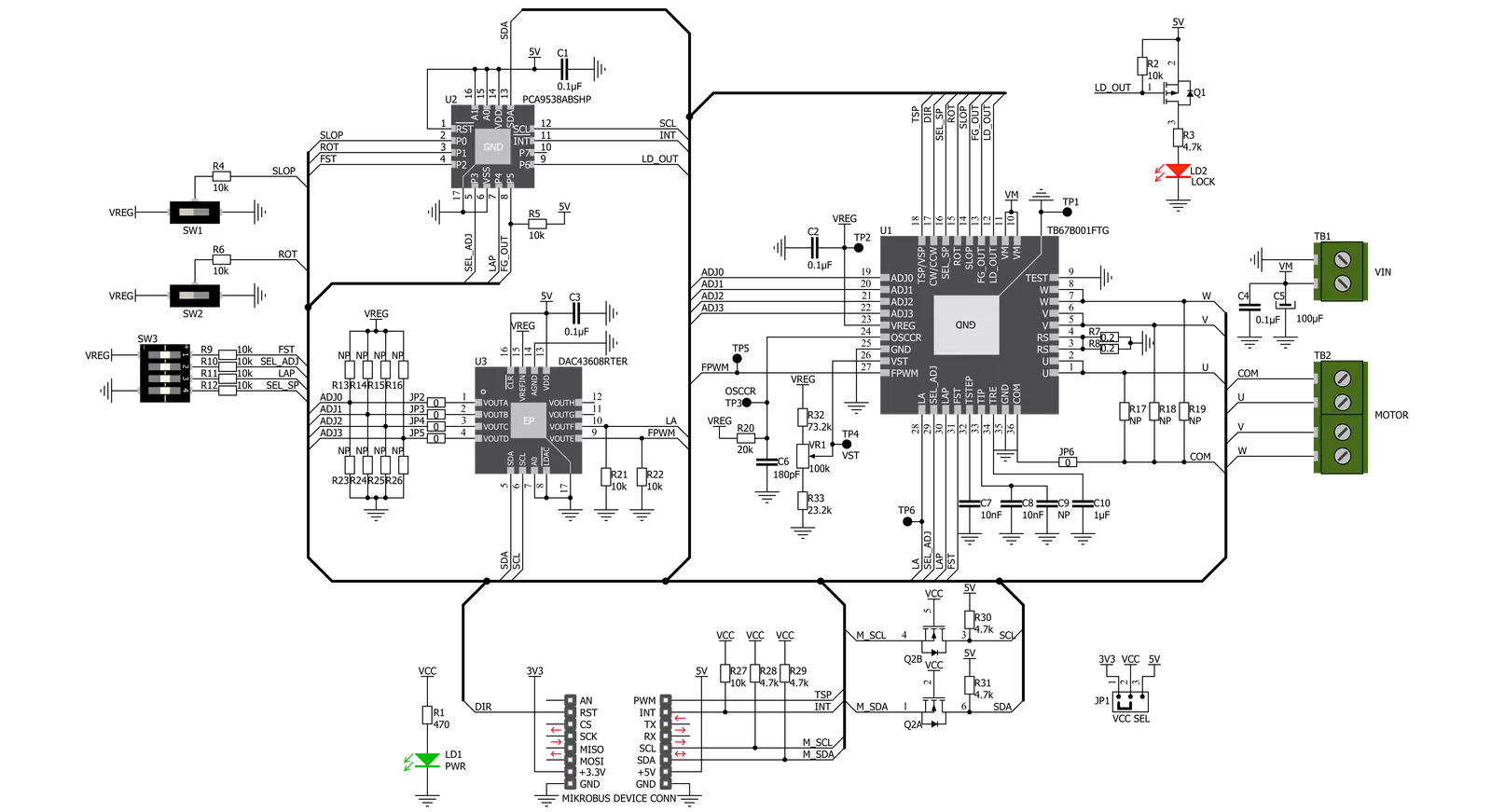
Brushless 14 Click is based on the TB67B001FTG, a three-phase PWM chopper driver for sensorless brushless motors from Toshiba Semiconductor. It controls motor rotation speed by changing the PWM duty cycle based on the speed control input. This Click board™ offers an energy-saving solution and quiet motor operation in brushless DC (BLDC) motors for various applications. The TSP signal, routed to the PWM signal of the mikroBUS™ socket, starts up and stops the motor operation and controls the output PWM duty to control the rotation speed of the motor. The procedure moves as follows: DC resolution mode - Forced commutation mode - Sensorless mode. Start-Up may fail when the initial rotor position is irregular because they do not synchronize in the forced commutation mode. In this case, adjustment to synchronize the forced commutation frequency to the motor rotation is necessary by adjusting the FST signal of the TB67B001FTG and the input voltage of the VST pin through the VR1 potentiometer to move the operation to the Sensorless mode. In forced commutation mode in Start-Up, the motor operates under the following condition: lead angle = 0°, 120° commutation, and without soft switching. When the process switches to the Sensorless mode, the operation changes automatically to the configured mode by setting the LA pin, LAP, and SLOP switches. SLOP and LAP
switches can select six types of drives (120°, 135°, and 150° commutation with and without soft switching). The TSP pin can select pulse duty control or analog voltage control by the SP pin of the SW3 switch. Besides, the TSP signal can adjust the output PWM duty by the configuration of ADJ0-3 channels done by DAC43608, a low-power, eight-channel, digital-to-analog converter. The desired value on the lead angle LA pin the TC78B042FTG and FPWM (output PWM frequency selection) is also obtained by the DAC3608, which establishes communication with MCU via I2C serial communication. The rotation speed of lead angle switching is selectable through the onboard ROT switch. When the most appropriate lead angle is set, the efficiency is improved, and the noise is reduced. In addition to I2C communication, several GPIO pins connected to the mikroBUS™ socket pins are also used. A DIR pin can switch the rotation direction of the motor, routed to the RST signal of the mikroBUS™ socket. While switching the rotation direction, first stop the motor, turn off the output by the TSP pin, and then switch the rotation direction by changing the configuration of the DIR pin. Besides, it is possible to detect motor lock events where the indication of such a condition is performed using the LED indicator labeled as LOCK and rotation speed, where the information is forwarded to the
MCU via the PCA9538 expander port. The user is left with the option of adding pull-up (R13-R16) or pull-down (R23-R26) resistors as desired for their applications and activating and deactivating the selected ADJ channels using jumper JP2-JP5. Also, when the motor is vibrating by an external factor, it may not start operating normally. In such a case, the motor can start operating normally by adding the external resistances of R17-R19 to provide the offset voltage in the position detection comparator inside the TB67B001FTG. Brushless 14 Click supports an external power supply for the motor, which can be connected to the input terminal labeled as VM and should be within the range of 5.5V to 22V. The next ones marked with U, V, W, and COM are terminals on which the BLDC motor needs to be connected. The absolute maximum rating of the power supply voltage is 25V (3A maximum current), which must not be exceeded, even for a moment. Do not exceed any of these ratings! This Click board™ can operate with either 3.3V or 5V logic voltage levels selected via the VCC SEL jumper. This way, both 3.3V and 5V capable MCUs can use the communication lines properly. This Click board™ comes equipped with a library containing easy-to-use functions and an example code that can be used, as a reference, for further development.

Features overview
Development board
EasyAVR v7 is the seventh generation of AVR development boards specially designed for the needs of rapid development of embedded applications. It supports a wide range of 16-bit AVR microcontrollers from Microchip and has a broad set of unique functions, such as a powerful onboard mikroProg programmer and In-Circuit debugger over USB. The development board is well organized and designed so that the end-user has all the necessary elements in one place, such as switches, buttons, indicators, connectors, and others. With four different connectors for each port, EasyAVR v7 allows you to connect accessory boards, sensors, and custom electronics more
efficiently than ever. Each part of the EasyAVR v7 development board contains the components necessary for the most efficient operation of the same board. An integrated mikroProg, a fast USB 2.0 programmer with mikroICD hardware In-Circuit Debugger, offers many valuable programming/debugging options and seamless integration with the Mikroe software environment. Besides it also includes a clean and regulated power supply block for the development board. It can use a wide range of external power sources, including an external 12V power supply, 7-12V AC or 9-15V DC via DC connector/screw terminals, and a power source via the USB Type-B (USB-B)
connector. Communication options such as USB-UART and RS-232 are also included, alongside the well-established mikroBUS™ standard, three display options (7-segment, graphical, and character-based LCD), and several different DIP sockets which cover a wide range of 16-bit AVR MCUs. EasyAVR v7 is an integral part of the Mikroe ecosystem for rapid development. Natively supported by Mikroe software tools, it covers many aspects of prototyping and development thanks to a considerable number of different Click boards™ (over a thousand boards), the number of which is growing every day.

Microcontroller Overview
MCU Card / MCU

Architecture
AVR
MCU Memory (KB)
64
Silicon Vendor
Microchip
Pin count
40
RAM (Bytes)
4096
You complete me!
Accessories
Brushless DC (BLDC) Motor with a Hall sensor represents a high-performance motor from the 42BLF motor series. This motor, wired in a star configuration, boasts a Hall Effect angle of 120°, ensuring precise and reliable performance. With a compact motor length of 47mm and a lightweight design tipping the scales at just 0.29kg, this BLDC motor is engineered to meet your needs. Operating flawlessly at a voltage rating of 24VDC and a speed range of 4000 ± 10% RPM, this motor offers consistent and dependable power. It excels in a normal operational temperature range from -20 to +50°C, maintaining efficiency with a rated current of 1.9A. Also, this product seamlessly integrates with all Brushless Click boards™ and those that require BLDC motors with Hall sensors.

Used MCU Pins
mikroBUS™ mapper
Take a closer look
Schematic
Step by step
Project assembly

Start by selecting your development board and Click board™. Begin with the EasyAVR v7 as your development board.


Track your results in real time
Application Output
After pressing the "FLASH" button on the left-side panel, it is necessary to open the UART terminal to display the achieved results. By clicking on the Tools icon in the right-hand panel, multiple different functions are displayed, among which is the UART Terminal. Click on the offered "UART Terminal" icon.

Once the UART terminal is opened, the window takes on a new form. At the top of the tab are two buttons, one for adjusting the parameters of the UART terminal and the other for connecting the UART terminal. The tab's lower part is reserved for displaying the achieved results. Before connecting, the terminal has a Disconnected status, indicating that the terminal is not yet active. Before connecting, it is necessary to check the set parameters of the UART terminal. Click on the "OPTIONS" button.

In the newly opened UART Terminal Options field, we check if the terminal settings are correct, such as the set port and the Baud rate of UART communication. If the data is not displayed properly, it is possible that the Baud rate value is not set correctly and needs to be adjusted to 115200. If all the parameters are set correctly, click on "CONFIGURE".

The next step is to click on the "CONNECT" button, after which the terminal status changes from Disconnected to Connected in green, and the data is displayed in the Received data field.

Software Support
Library Description
This library contains API for Brushless 14 Click driver.
Key functions:
brushless14_set_duty_cycle- This function sets PWM duty cyclebrushless14_set_la- This function set lead angle setting inputbrushless14_set_dir- This function set dirrection pin state
Open Source
Code example
This example can be found in NECTO Studio. Feel free to download the code, or you can copy the code below.
/*!
 * @file main.c
 * @brief Brushless14 Click example
 *
 * # Description
 * This application example showcases ability of the device to control motor,
 * It's speed and rotation direction. Also it gives user ability to change other
 * configuration parameters.
 *
 * The demo application is composed of two sections :
 *
 * ## Application Init
 * Initialization of communication modules (I2C, PWM, UART) and additional
 * pins (INT, DIR). It reads ID from DAC ic to confirm communcation. Then
 * configures device for control.
 *
 * ## Application Task
 * Drives motor using PWM from 10% duty cycle to 100% and back to 0%.
 * Increment is done by 10% in span of 2 seconds. Whenever application gets
 * to 0% duty cycle it chages direction of rotation.
 *
 * @author Luka Filipovic
 *
 */

#include "board.h"
#include "log.h"
#include "brushless14.h"

static brushless14_t brushless14;
static log_t logger;

void application_init ( void )
{
    log_cfg_t log_cfg;  /**< Logger config object. */
    brushless14_cfg_t brushless14_cfg;  /**< Click config object. */

    /**
     * Logger initialization.
     * Default baud rate: 115200
     * Default log level: LOG_LEVEL_DEBUG
     * @note If USB_UART_RX and USB_UART_TX
     * are defined as HAL_PIN_NC, you will
     * need to define them manually for log to work.
     * See @b LOG_MAP_USB_UART macro definition for detailed explanation.
     */
    LOG_MAP_USB_UART( log_cfg );
    log_init( &logger, &log_cfg );
    log_info( &logger, " Application Init " );

    // Click initialization.
    brushless14_cfg_setup( &brushless14_cfg );
    BRUSHLESS14_MAP_MIKROBUS( brushless14_cfg, MIKROBUS_1 );
    err_t init_flag = brushless14_init( &brushless14, &brushless14_cfg );
    if ( I2C_MASTER_ERROR == init_flag )
    {
        log_error( &logger, " Application Init Error. " );
        log_info( &logger, " Please, run program again... " );

        for ( ; ; );
    }

    uint16_t data_read = 0;
    brushless14_dac_read( &brushless14, 0x02, &data_read);
    if ( BRUSHLESS14_DAC_ID != data_read )
    {
        log_error( &logger, " Communication. " );
    }

    brushless14_default_cfg ( &brushless14 );

    Delay_ms( 1000 );
    log_info( &logger, " Application Task " );
}

void application_task ( void )
{
    static int8_t duty_cnt = 1;
    static int8_t duty_inc = 1;
    static uint8_t direction = 0;
    float duty = duty_cnt / 10.0;

    brushless14_set_duty_cycle ( &brushless14, duty );
    log_printf( &logger, "> Duty: %d%%\r\n", ( uint16_t )( duty_cnt * 10 ) );

    Delay_ms( 2000 );

    if ( 10 == duty_cnt )
    {
        duty_inc = -1;
    }
    else if ( 0 == duty_cnt )
    {
        duty_inc = 1;
        direction = !direction;
        brushless14_set_dir( &brushless14, direction );
    }
    duty_cnt += duty_inc;
}

void main ( void )
{
    application_init( );

    for ( ; ; )
    {
        application_task( );
    }
}

// ------------------------------------------------------------------------ END


