Achieve precise spectral identification and color matching with AS7341 and PIC32MZ1024EFH064
Shades of brilliance: Unmasking the spectral story

Published Sep 24, 2023
Click board™
Spectrometer Click
Dev. board
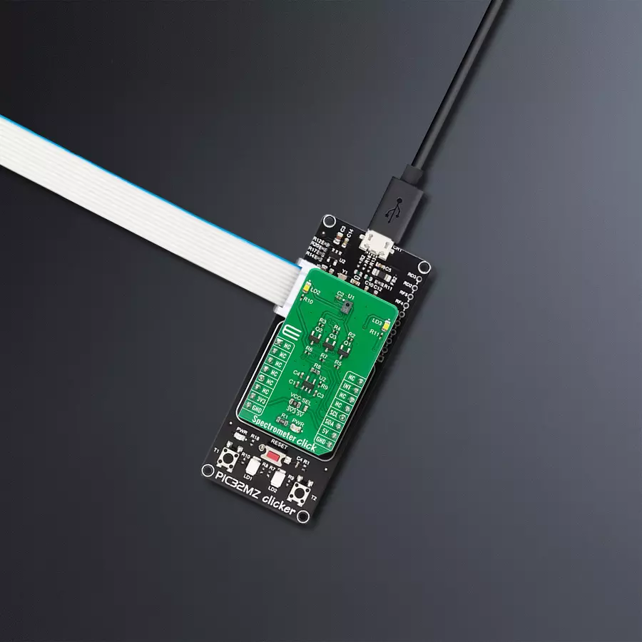
PIC32MZ clicker
Compiler
NECTO Studio
MCU
PIC32MZ1024EFH064
Unleash the power of spectral analysis for accurate color matching, ensuring consistent and flawless results in design, manufacturing, and quality control
A
A
Hardware Overview
How does it work?
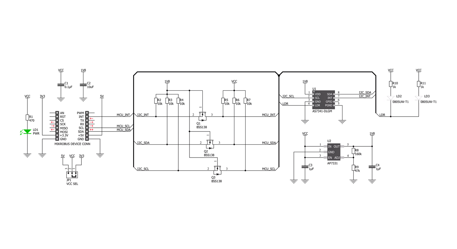
Spectrometer Click is based on the AS7341, 11-channel spectral sensor frontend from ams OSRAM. This IC features six independent optical channels with a dedicated 16-bit light-to-frequency converter. The gain and integration time of the six channels can be adjusted with the serial interface. Wait time can be programmed to automatically set a delay between two consecutive spectral measurements and reduce overall power consumption. A multiplexer (SMUX) can access the other available channels, connecting them to one of the internal ADCs. It also features a 4x4-photodiode array. On top and below the photodiode array are two photodiodes with dedicated functions such as flicker detection and near-infrared response. This Click board includes an LDO AP7331 to provide the 1.8 V supply voltage for the AS7341 and 3 N-Channel MOSFET BSS138 for voltage level translation. The AS7341,
interrupt-driven IC, is controlled and monitored by registers accessed through the I²C serial interface. These registers provide device control functions and can be read to determine device status and data acquisition. The device supports 7-bit chip addressing and standard and full-speed clock frequency modes. It possesses eight optical channels distributed over the visible spectral range, clear and NIR channels to accurately measure and match colors, and a configurable sleep mode. The device also integrates a dedicated channel to detect 50Hz or 60Hz ambient light flicker. The flicker detection engine can also buffer data for calculating other flicker frequencies externally. Upon power-up, the Spectrometer Click initializes. During initialization (typically 200μs), the device will deterministically send NAK on I²C and cannot accept I²C transactions. All communication with the device must be delayed, and all outputs
from the device must be ignored, including interrupts. After initialization, the device enters the SLEEP state (the internal oscillator and other circuitry are inactive, resulting in ultra-low power consumption). Once the Power ON bit is enabled, the device enters the IDLE state where the internal oscillator and attendant circuitry are active, but power consumption remains low. Whenever the spectral measurement is enabled, the device enters the ACTIVE state. If the spectral measurement is disabled, the device returns to the IDLE state. This Click board™ can operate with either 3.3V or 5V logic voltage levels selected via the VCC SEL jumper. This way, both 3.3V and 5V capable MCUs can use the communication lines properly. Also, this Click board™ comes equipped with a library containing easy-to-use functions and an example code that can be used as a reference for further development.


Features overview
Development board
PIC32MZ Clicker is a compact starter development board that brings the flexibility of add-on Click boards™ to your favorite microcontroller, making it a perfect starter kit for implementing your ideas. It comes with an onboard 32-bit PIC32MZ microcontroller with FPU from Microchip, a USB connector, LED indicators, buttons, a mikroProg connector, and a header for interfacing with external electronics. Thanks to its compact design with clear and easy-recognizable silkscreen markings, it provides a fluid and immersive working experience, allowing access anywhere and under
any circumstances. Each part of the PIC32MZ Clicker development kit contains the components necessary for the most efficient operation of the same board. In addition to the possibility of choosing the PIC32MZ Clicker programming method, using USB HID mikroBootloader, or through an external mikroProg connector for PIC, dsPIC, or PIC32 programmer, the Clicker board also includes a clean and regulated power supply module for the development kit. The USB Micro-B connection can provide up to 500mA of current, which is more than enough to operate all onboard
and additional modules. All communication methods that mikroBUS™ itself supports are on this board, including the well-established mikroBUS™ socket, reset button, and several buttons and LED indicators. PIC32MZ Clicker is an integral part of the Mikroe ecosystem, allowing you to create a new application in minutes. Natively supported by Mikroe software tools, it covers many aspects of prototyping thanks to a considerable number of different Click boards™ (over a thousand boards), the number of which is growing every day.

Microcontroller Overview
MCU Card / MCU

Architecture
PIC32
MCU Memory (KB)
1024
Silicon Vendor
Microchip
Pin count
64
RAM (Bytes)
524288
Used MCU Pins
mikroBUS™ mapper
Take a closer look
Click board™ Schematic
Step by step
Project assembly

Start by selecting your development board and Click board™. Begin with the PIC32MZ clicker as your development board.


Software Support
Library Description
This library contains API for Spectrometer Click driver.
Key functions:
spectrometer_raw_rd_val_mode_1- This function is used to read out channels with SMUX configration 1; F1-F4, Clearspectrometer_raw_rd_val_mode_2- This function is used to read out channels with SMUX configration 2; F5-F8, Clearspectrometer_flicker_detection- This function is used to detect flicker for 100 and 120 Hz.
Open Source
Code example
The complete application code and a ready-to-use project are available through the NECTO Studio Package Manager for direct installation in the NECTO Studio. The application code can also be found on the MIKROE GitHub account.
/*!
 * \file
 * \brief Spectrometer Click example
 *
 * # Description
 * This Click is an 11-channel spectrometer for spectral identification and color matching. The
 * spectral response is defined in the wavelengths from approximately 350nm to 1000nm. 8 optical
 * channels cover the visible spectrum, one channel can be used to measure near infra-red light
 * and one channel is a photo diode without filter (“clear”). The device also integrates a
 * dedicated channel to detect 50Hz or 60Hz ambient light flicker.
 *
 * The demo application is composed of two sections :
 *
 * ## Application Init
 * Initalizes I2C driver, performs safety check and makes an initial log.
 *
 * ## Application Task
 * This example shows the capabilities of the Spectrometer Click
 * by reading out channels with SMUX configrations 1 and 2, detecting
 * flicker for 100 and 120 Hz and displaying data via USART terminal.
 *
 *
 * \author MikroE Team
 *
 */
// ------------------------------------------------------------------- INCLUDES

#include "board.h"
#include "log.h"
#include "spectrometer.h"

// ------------------------------------------------------------------ VARIABLES

static spectrometer_t spectrometer;
static log_t logger;

static uint8_t id_val;
static uint16_t ch_0;
static uint16_t ch_1;
static uint16_t ch_2;
static uint16_t ch_3;
static uint16_t ch_4;
static uint8_t f_val;
static uint8_t adc_buf[ 13 ];

// ------------------------------------------------------ APPLICATION FUNCTIONS

void application_init ( void )
{
    log_cfg_t log_cfg;
    spectrometer_cfg_t cfg;

    /**
     * Logger initialization.
     * Default baud rate: 115200
     * Default log level: LOG_LEVEL_DEBUG
     * @note If USB_UART_RX and USB_UART_TX
     * are defined as HAL_PIN_NC, you will
     * need to define them manually for log to work.
     * See @b LOG_MAP_USB_UART macro definition for detailed explanation.
     */
    LOG_MAP_USB_UART( log_cfg );
    log_init( &logger, &log_cfg );
    log_info( &logger, "---- Application Init ----" );

    //  Click initialization.

    spectrometer_cfg_setup( &cfg );
    SPECTROMETER_MAP_MIKROBUS( cfg, MIKROBUS_1 );
    spectrometer_init( &spectrometer, &cfg );
    Delay_ms ( 100 );

    spectrometer_generic_read ( &spectrometer, SPECTROMETER_ID, &id_val, 1 );
    if ( id_val == SPECTROMETER_ID_VALUE )
    {
        log_printf( &logger, "-------------------------\r\n" );
        log_printf( &logger, "   Spectrometer  Click   \r\n" );
        log_printf( &logger, "-------------------------\r\n" );
    }
    else
    {
        log_printf( &logger, "-------------------------\r\n" );
        log_printf( &logger, "     FATAL  ERROR!!!     \r\n" );
        log_printf( &logger, "-------------------------\r\n" );
        for ( ; ; );
    }
    Delay_ms ( 100 );

    spectrometer_def_cfg( &spectrometer );
    Delay_ms ( 100 );
}

void application_task ( void )
{
    spectrometer_raw_rd_val_mode_1( &spectrometer, &adc_buf[ 0 ] );

    ch_0 = adc_buf[ 1 ];
    ch_0 <<= 8;
    ch_0 |= adc_buf[ 0 ];
    log_printf( &logger, " ADC0/F1 : %u\r\n", ch_0 );

    ch_1 = adc_buf[ 3 ];
    ch_1 <<= 8;
    ch_1 |= adc_buf[ 2 ];
    log_printf( &logger, " ADC1/F2 : %u\r\n", ch_1 );

    ch_2 = adc_buf[ 5 ];
    ch_2 <<= 8;
    ch_2 |= adc_buf[ 4 ];
    log_printf( &logger, " ADC2/F3 : %u\r\n", ch_2 );

    ch_3 = adc_buf[ 7 ];
    ch_3 <<= 8;
    ch_3 |= adc_buf[ 6 ];
    log_printf( &logger, " ADC3/F4 : %u\r\n", ch_3 );

    ch_4 = adc_buf[ 9 ];
    ch_4 <<= 8;
    ch_4 |= adc_buf[ 8 ];
    log_printf( &logger, " ADC4/Clear : %u\r\n", ch_4 );

    spectrometer_raw_rd_val_mode_2( &spectrometer, &adc_buf[ 0 ] );

    ch_0 = adc_buf[ 1 ];
    ch_0 <<= 8;
    ch_0 |= adc_buf[ 0 ];
    log_printf( &logger, " ADC0/F5 : %u\r\n", ch_0 );

    ch_1 = adc_buf[ 3 ];
    ch_1 <<= 8;
    ch_1 |= adc_buf[ 2 ];
    log_printf( &logger, " ADC1/F6 : %u\r\n", ch_1 );

    ch_2 = adc_buf[ 5 ];
    ch_2 <<= 8;
    ch_2 |= adc_buf[ 4 ];
    log_printf( &logger, " ADC2/F7 : %u\r\n", ch_2 );

    ch_3 = adc_buf[ 7 ];
    ch_3 <<= 8;
    ch_3 |= adc_buf[ 6 ];
    log_printf( &logger, " ADC3/F8 : %u\r\n", ch_3 );

    ch_4 = adc_buf[ 9 ];
    ch_4 <<= 8;
    ch_4 |= adc_buf[ 8 ];
    log_printf( &logger, " ADC4/Clear : %u\r\n", ch_4 );

    f_val = spectrometer_flicker_detection( &spectrometer );

    log_printf( &logger, " Flicker : " );
    if ( f_val == SPECTROMETER_UNKNOWN_FREQ )
    {
        log_printf( &logger, "unknown\r\n" );
    }
    else if ( f_val == SPECTROMETER_DETECTED_100_HZ )
    {
        log_printf( &logger, "100 Hz detected\r\n" );
    }
    else if ( f_val == SPECTROMETER_DETECTED_120_HZ )
    {
        log_printf( &logger, "120 Hz detected\r\n" );
    }
    else
    {
        log_printf( &logger, "Error in reading\r\n" );
    }

    log_printf( &logger, "-----------------\r\n" );
    Delay_ms ( 1000 );
}

int main ( void )
{
    /* Do not remove this line or clock might not be set correctly. */
    #ifdef PREINIT_SUPPORTED
    preinit();
    #endif

    application_init( );

    for ( ; ; )
    {
        application_task( );
    }

    return 0;
}


// ------------------------------------------------------------------------ END
Additional Support
Resources
Category:Optical


