Harness the power of infrared beaconing using VSMB2948SL and ATmega328P
Beacon beyond: Elevate your app with IR magic

Published Feb 14, 2024
Click board™
IR Beacon Click
Dev. board
Arduino UNO Rev3
Compiler
NECTO Studio
MCU
ATmega328P
Facilitate secure and high-speed data transfer between devices, supporting various data-sharing use cases
A
A
Hardware Overview
How does it work?
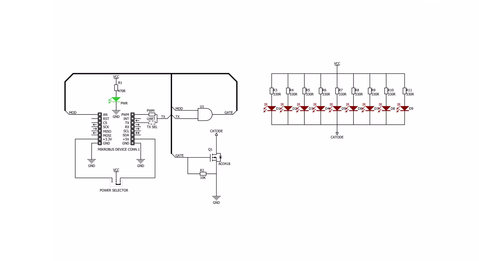
IR Beacon Click is based on the nine VSMB2948SLs, high-speed infrared emitting diodes from Vishay Semiconductors. The VSMB2948SL is a 940nm wavelength infrared emitting diode in a GaAIAs multi-quantum well (MQW) technology with high radiant power, high radiant intensity, and high speed molded in a clear untinted package with a lens. This kind of architecture allows the IR wave to have a half-intensity angle of ±25 degrees and a range of
up to half of a meter that can be increased by stacking multiple IR Beacon Clicks onto the same mikroBUS™ socket. The IR Beacon uses either UART or PWM lines of the mikroBUS™ socket, selected over the TX SEL jumpers, with PWM chosen by default, to allow the host MCU to transmit a signal to a target receiver. The mainboard MCU drives the infrared diodes through the MOD pin, providing a carrier signal that can be adjusted to match the frequency.
This Click board™ can operate with either 3.3V or 5V logic voltage levels selected via the PWR SEL jumper. This way, both 3.3V and 5V capable MCUs can use the communication lines properly. Also, this Click board™ comes equipped with a library containing easy-to-use functions and an example code that can be used as a reference for further development.
Features overview
Development board
Arduino UNO is a versatile microcontroller board built around the ATmega328P chip. It offers extensive connectivity options for various projects, featuring 14 digital input/output pins, six of which are PWM-capable, along with six analog inputs. Its core components include a 16MHz ceramic resonator, a USB connection, a power jack, an
ICSP header, and a reset button, providing everything necessary to power and program the board. The Uno is ready to go, whether connected to a computer via USB or powered by an AC-to-DC adapter or battery. As the first USB Arduino board, it serves as the benchmark for the Arduino platform, with "Uno" symbolizing its status as the
first in a series. This name choice, meaning "one" in Italian, commemorates the launch of Arduino Software (IDE) 1.0. Initially introduced alongside version 1.0 of the Arduino Software (IDE), the Uno has since become the foundational model for subsequent Arduino releases, embodying the platform's evolution.

Microcontroller Overview
MCU Card / MCU

Architecture
AVR
MCU Memory (KB)
32
Silicon Vendor
Microchip
Pin count
28
RAM (Bytes)
2048
You complete me!
Accessories
Click Shield for Arduino UNO has two proprietary mikroBUS™ sockets, allowing all the Click board™ devices to be interfaced with the Arduino UNO board without effort. The Arduino Uno, a microcontroller board based on the ATmega328P, provides an affordable and flexible way for users to try out new concepts and build prototypes with the ATmega328P microcontroller from various combinations of performance, power consumption, and features. The Arduino Uno has 14 digital input/output pins (of which six can be used as PWM outputs), six analog inputs, a 16 MHz ceramic resonator (CSTCE16M0V53-R0), a USB connection, a power jack, an ICSP header, and reset button. Most of the ATmega328P microcontroller pins are brought to the IO pins on the left and right edge of the board, which are then connected to two existing mikroBUS™ sockets. This Click Shield also has several switches that perform functions such as selecting the logic levels of analog signals on mikroBUS™ sockets and selecting logic voltage levels of the mikroBUS™ sockets themselves. Besides, the user is offered the possibility of using any Click board™ with the help of existing bidirectional level-shifting voltage translators, regardless of whether the Click board™ operates at a 3.3V or 5V logic voltage level. Once you connect the Arduino UNO board with our Click Shield for Arduino UNO, you can access hundreds of Click boards™, working with 3.3V or 5V logic voltage levels.

Used MCU Pins
mikroBUS™ mapper
Take a closer look
Click board™ Schematic
Step by step
Project assembly

Start by selecting your development board and Click board™. Begin with the Arduino UNO Rev3 as your development board.


Software Support
Library Description
This library contains API for IR Beacon Click driver.
Key functions:
irbeacon_enable_mod- Enable MOD functionirbeacon_disable_mod- Disable MOD functionirbeacon_reset_mod- Reset MOD function
Open Source
Code example
The complete application code and a ready-to-use project are available through the NECTO Studio Package Manager for direct installation in the NECTO Studio. The application code can also be found on the MIKROE GitHub account.
/*!
 * @file
 * @brief IrBeacon Click example
 *
 * # Description
 * This library contains an API for the IrBeacon Click driver.
 * This application is suitable for high pulse current operation.
 *
 * The demo application is composed of two sections :
 *
 * ## Application Init
 * Enables GPIO and PWM, sets the frequency and duty cycle and enables PWM.
 *
 * ## Application Task
 * This is a example which demonstrates the use of IR Beacon Click board.
 * It shows how to enable the device and gradualy increase the duty cycle.
 * Results are being sent to the Usart Terminal where you can track their changes.
 *
 * @author Nikola Peric
 *
 */
// ------------------------------------------------------------------- INCLUDES

#include "board.h"
#include "log.h"
#include "irbeacon.h"

// ------------------------------------------------------------------ VARIABLES

static irbeacon_t irbeacon;
static log_t logger;

// ------------------------------------------------------ APPLICATION FUNCTIONS

void application_init ( void )
{
    log_cfg_t log_cfg;
    irbeacon_cfg_t cfg;

    /**
     * Logger initialization.
     * Default baud rate: 115200
     * Default log level: LOG_LEVEL_DEBUG
     * @note If USB_UART_RX and USB_UART_TX
     * are defined as HAL_PIN_NC, you will
     * need to define them manually for log to work.
     * See @b LOG_MAP_USB_UART macro definition for detailed explanation.
     */
    LOG_MAP_USB_UART( log_cfg );
    log_init( &logger, &log_cfg );
    log_info( &logger, "---- Application Init ----" );

    //  Click initialization.

    irbeacon_cfg_setup( &cfg );
    IRBEACON_MAP_MIKROBUS( cfg, MIKROBUS_1 );
    irbeacon_init( &irbeacon, &cfg );
    irbeacon_pwm_start( &irbeacon );

    log_info( &logger, "---- Application Task ----" );
    Delay_ms ( 1000 );
}

void application_task ( void )
{
    static int8_t duty_cnt = 1;
    static int8_t duty_inc = 1;
    float duty = duty_cnt / 10.0;

    irbeacon_set_duty_cycle ( &irbeacon, duty );
    irbeacon_enable_mod( &irbeacon );
    log_printf( &logger, "Duty: %d%%\r\n", ( uint16_t )( duty_cnt * 10 ) );
    Delay_ms ( 500 );

    if ( 10 == duty_cnt )
    {
        duty_inc = -1;
    }
    else if ( 0 == duty_cnt )
    {
        irbeacon_disable_mod( &irbeacon );
        duty_inc = 1;
    }
    duty_cnt += duty_inc;
}

int main ( void )
{
    /* Do not remove this line or clock might not be set correctly. */
    #ifdef PREINIT_SUPPORTED
    preinit();
    #endif

    application_init( );

    for ( ; ; )
    {
        application_task( );
    }

    return 0;
}

// ------------------------------------------------------------------------ END
Additional Support
Resources
Category:Optical


