Immerse yourself in the world of accurate color perception using AS73211 and PIC18F57Q43
Bringing colors to life

Published Feb 13, 2024
Click board™
Color 6 Click
Dev. board
Curiosity Nano with PIC18F57Q43
Compiler
NECTO Studio
MCU
PIC18F57Q43
Experience the world of colors with unparalleled accuracy and precision through our advanced color sensing technology
A
A
Hardware Overview
How does it work?
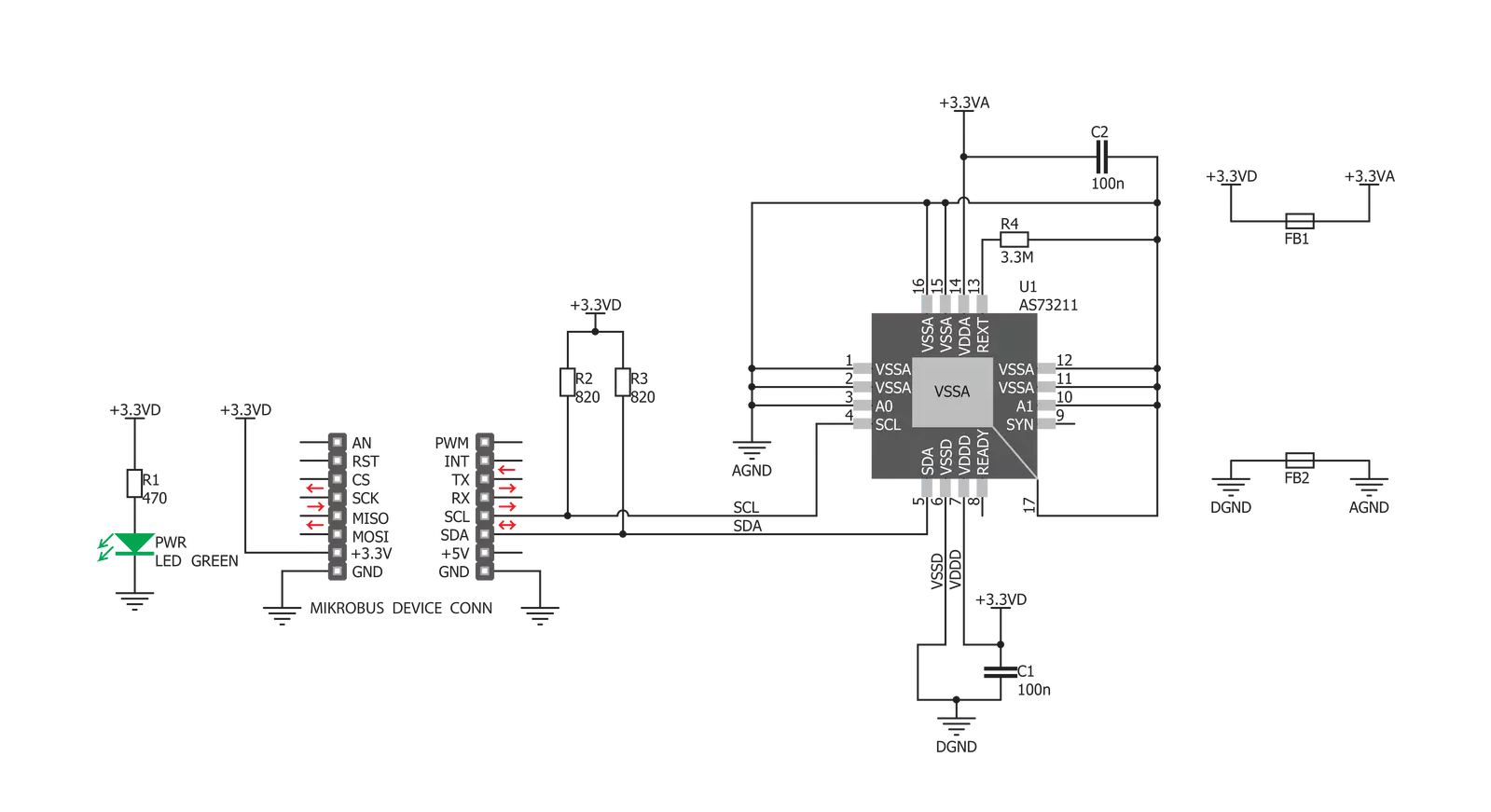
Color 6 Click is based on the AS73211, an XYZ true color sensor from ams OSRAM. This sensor is produced by using the proprietary JENCOLOR™ filter technology, developed by this company. The sensor uses three 24bit ADC converters, which convert the measurement from the photodiodes. The photodiodes are covered by the optical filters. These filters isolate X, Y and Z color components, providing CIE 1931/DIN 5033 standard compliant color response, which matches the color response of the human eye. The irradiance responsivity (GAIN) can be set in a range of 12 steps by a factor of 2 for each step (up to 2048 times), providing a huge dynamic range, up to 3.43E+10:1. To perform the measurement, the device has to be set up first. After the POR (Power On Reset), the device is set up in the Config mode. After the successful configuration of the measurement parameters, the Measurement mode can be activated, by setting the corresponding bits in the Operation State Register (OSR). The measurement itself is stored as 16bit information, although the conversion data is 24bit wide. Without using an internal divider, only the 16 least significant bits of information are available. By employing the divider, it is possible to dynamically shift the information so the most relevant bits are accessed via the 16bit registers. There are two modes of
measurement available on this Click board™. It can use the CONT (continuous measurement), or the CMD (single measurement) measurement modes. The CONT mode outputs data continuously, using a time delay determined by the content of the BREAK register, while the CMD mode allows one measurement to be performed per command. After a single measurement is performed, the device can fall back to the Power Down or Standby state, while working in CMD mode. This is determined by the appropriate bits in the configuration registers and allows for a lower power consumption if required by the application. To allow for the best performance and most accurate measurements, the surface of the board and especially the sensor IC itself, should always stay clean and without scratches, as dirt and moisture can alter the light penetration through the filters. In addition, the manufacturer recommends that the angle of incidence stays less than 10° since the sensor IC has an aperture angle (beam width) of nearly 90°. If the angle of incidence is greater than advised, the filter shifting might occur, introducing distortion and affecting the measurement results. The spectral filters of this sensor are specialized for working with the broadband source of light, and measurement of the narrowband light sources should not be
performed by this sensor. The internal thermal sensor allows the temperature compensation to be calculated, achieving the most accurate measurements. This ADC outputs 12bit data, which can be read from the appropriate register via the I2C interface. The Click board™ itself uses a very low number of external components. In fact, it only uses one external resistor, which is used for providing the reference voltage for the internal sections of the IC, along with few resistors, used for pulling the I2C lines to a HIGH logic level when not asserted and ferrite beds, which isolate noise between the analog and digital GND. The low number of external components simplify the design with this IC, allowing it to be used in a wide range of portable applications. I2C bus lines are routed to the appropriate mikroBUS™ pins, offering simple and reliable interfacing with the host MCU. Please note that this Click board™ can work only with 3.3V MCUs and it is not 5V tolerant. The device datasheet contains all the necessary information about the registers and their values. However, the Click board™ comes supported by a library, which contains functions which simplify the development of the applications, cutting time to market.


Features overview
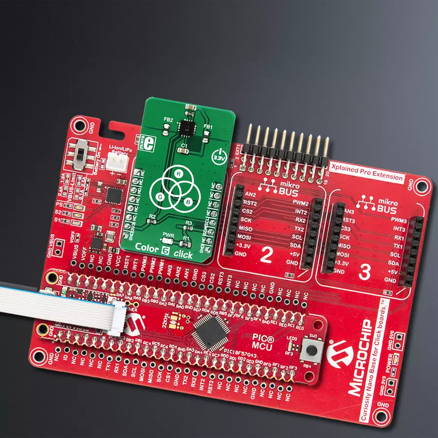
Development board
PIC18F57Q43 Curiosity Nano evaluation kit is a cutting-edge hardware platform designed to evaluate microcontrollers within the PIC18-Q43 family. Central to its design is the inclusion of the powerful PIC18F57Q43 microcontroller (MCU), offering advanced functionalities and robust performance. Key features of this evaluation kit include a yellow user LED and a responsive
mechanical user switch, providing seamless interaction and testing. The provision for a 32.768kHz crystal footprint ensures precision timing capabilities. With an onboard debugger boasting a green power and status LED, programming and debugging become intuitive and efficient. Further enhancing its utility is the Virtual serial port (CDC) and a debug GPIO channel (DGI
GPIO), offering extensive connectivity options. Powered via USB, this kit boasts an adjustable target voltage feature facilitated by the MIC5353 LDO regulator, ensuring stable operation with an output voltage ranging from 1.8V to 5.1V, with a maximum output current of 500mA, subject to ambient temperature and voltage constraints.

Microcontroller Overview
MCU Card / MCU

Architecture
PIC
MCU Memory (KB)
128
Silicon Vendor
Microchip
Pin count
48
RAM (Bytes)
8196
You complete me!
Accessories
Curiosity Nano Base for Click boards is a versatile hardware extension platform created to streamline the integration between Curiosity Nano kits and extension boards, tailored explicitly for the mikroBUS™-standardized Click boards and Xplained Pro extension boards. This innovative base board (shield) offers seamless connectivity and expansion possibilities, simplifying experimentation and development. Key features include USB power compatibility from the Curiosity Nano kit, alongside an alternative external power input option for enhanced flexibility. The onboard Li-Ion/LiPo charger and management circuit ensure smooth operation for battery-powered applications, simplifying usage and management. Moreover, the base incorporates a fixed 3.3V PSU dedicated to target and mikroBUS™ power rails, alongside a fixed 5.0V boost converter catering to 5V power rails of mikroBUS™ sockets, providing stable power delivery for various connected devices.

Used MCU Pins
mikroBUS™ mapper
Take a closer look
Click board™ Schematic
Step by step
Project assembly

Start by selecting your development board and Click board™. Begin with the Curiosity Nano with PIC18F57Q43 as your development board.


Software Support
Library Description
This library contains API for Color 6 Click driver.
Key functions:
color6_write_byte- This function write one byte in registercolor6_read_byte- This function reads one byte data from registercolor6_get_temperature- The measurement result is available as TEMP of the output result registers.
Open Source
Code example
The complete application code and a ready-to-use project are available through the NECTO Studio Package Manager for direct installation in the NECTO Studio. The application code can also be found on the MIKROE GitHub account.
/*!
 * \file
 * \brief Color6 Click example
 *
 * # Description
 *  Reads values from the X / Y / Z channel and
 *  converts to ee (input light irradiance regarding to the photodiode�s area
 *  within the conversion time interval) data.
 *
 * The demo application is composed of two sections :
 *
 * ## Application Init
 *  Initializes and configuration device for measurement.
 *
 * ## Application Task
 *  Reads values from the X / Y / Z channel and
 *  converts to ee (input light irradiance regarding to the photodiode�s area
 *  within the conversion time interval) data.
 *  This data logs on USB UART every 2 seconds.
 *
 * \author MikroE Team
 *
 */
// ------------------------------------------------------------------- INCLUDES

#include "board.h"
#include "log.h"
#include "color6.h"

// ------------------------------------------------------------------ VARIABLES

static color6_t color6;
static log_t logger;

uint16_t x_data = 0;
uint16_t y_data = 0;
uint16_t z_data = 0;
float ee_data;
float temperature;

// ------------------------------------------------------ APPLICATION FUNCTIONS

void application_init ( void )
{
    log_cfg_t log_cfg;
    color6_cfg_t cfg;

    /**
     * Logger initialization.
     * Default baud rate: 115200
     * Default log level: LOG_LEVEL_DEBUG
     * @note If USB_UART_RX and USB_UART_TX
     * are defined as HAL_PIN_NC, you will
     * need to define them manually for log to work.
     * See @b LOG_MAP_USB_UART macro definition for detailed explanation.
     */
    LOG_MAP_USB_UART( log_cfg );
    log_init( &logger, &log_cfg );
    log_info( &logger, "---- Application Init ----" );

    //  Click initialization.

    color6_cfg_setup( &cfg );
    COLOR6_MAP_MIKROBUS( cfg, MIKROBUS_1 );
    color6_init( &color6, &cfg );

    color6_software_reset( &color6 );
    color6_default_cfg ( &color6 );
    color6_go_to_measurement_mode( &color6 );
}

void application_task ( void )
{
    x_data = color6_read_data( &color6, COLOR6_MREG_MEASUREMENT_X_CHANNEL );
    log_printf( &logger, " Channel X :  %d \r\n ", x_data );

    ee_data = color6_converting_to_ee( &color6, COLOR6_MREG_MEASUREMENT_X_CHANNEL, x_data);
    log_printf( &logger, " Ee X channel data:   %f \r\n ", ee_data );

    y_data = color6_read_data( &color6, COLOR6_MREG_MEASUREMENT_Y_CHANNEL );
    log_printf( &logger, " Channel Y :  %d\r\n ", y_data );

    ee_data = color6_converting_to_ee( &color6, COLOR6_MREG_MEASUREMENT_Y_CHANNEL, y_data);
    log_printf( &logger, " Ee Y channel data:   %f \r\n", ee_data );

    z_data = color6_read_data( &color6, COLOR6_MREG_MEASUREMENT_Z_CHANNEL );
    log_printf( &logger, " Channel Z :  %d\r\n ", z_data );

    ee_data = color6_converting_to_ee( &color6, COLOR6_MREG_MEASUREMENT_Z_CHANNEL, z_data);
    log_printf( &logger, " Ee Z channel data:   %f\r\n ", ee_data );

    temperature = color6_get_temperature( &color6 );
    log_printf( &logger, " Temperature :  %f\r\n ", temperature );

    Delay_ms ( 1000 );
    Delay_ms ( 1000 );
}

int main ( void )
{
    /* Do not remove this line or clock might not be set correctly. */
    #ifdef PREINIT_SUPPORTED
    preinit();
    #endif

    application_init( );

    for ( ; ; )
    {
        application_task( );
    }

    return 0;
}


// ------------------------------------------------------------------------ END
Additional Support
Resources
Category:Optical


