Experience the future of IR serial data exchange with TFDU4101, MCP2120 and PIC32MZ2048EFM100
Send and receive Infrared (IR) serial data

Published Jan 23, 2024
Click board™
IrDA2 Click
Dev. board
Curiosity PIC32 MZ EF
Compiler
NECTO Studio
MCU
PIC32MZ2048EFM100
Achieve fast and stable infrared data communication, covering a more than 1m range and speeds up to 115.2 kbit/s
A
A
Hardware Overview
How does it work?
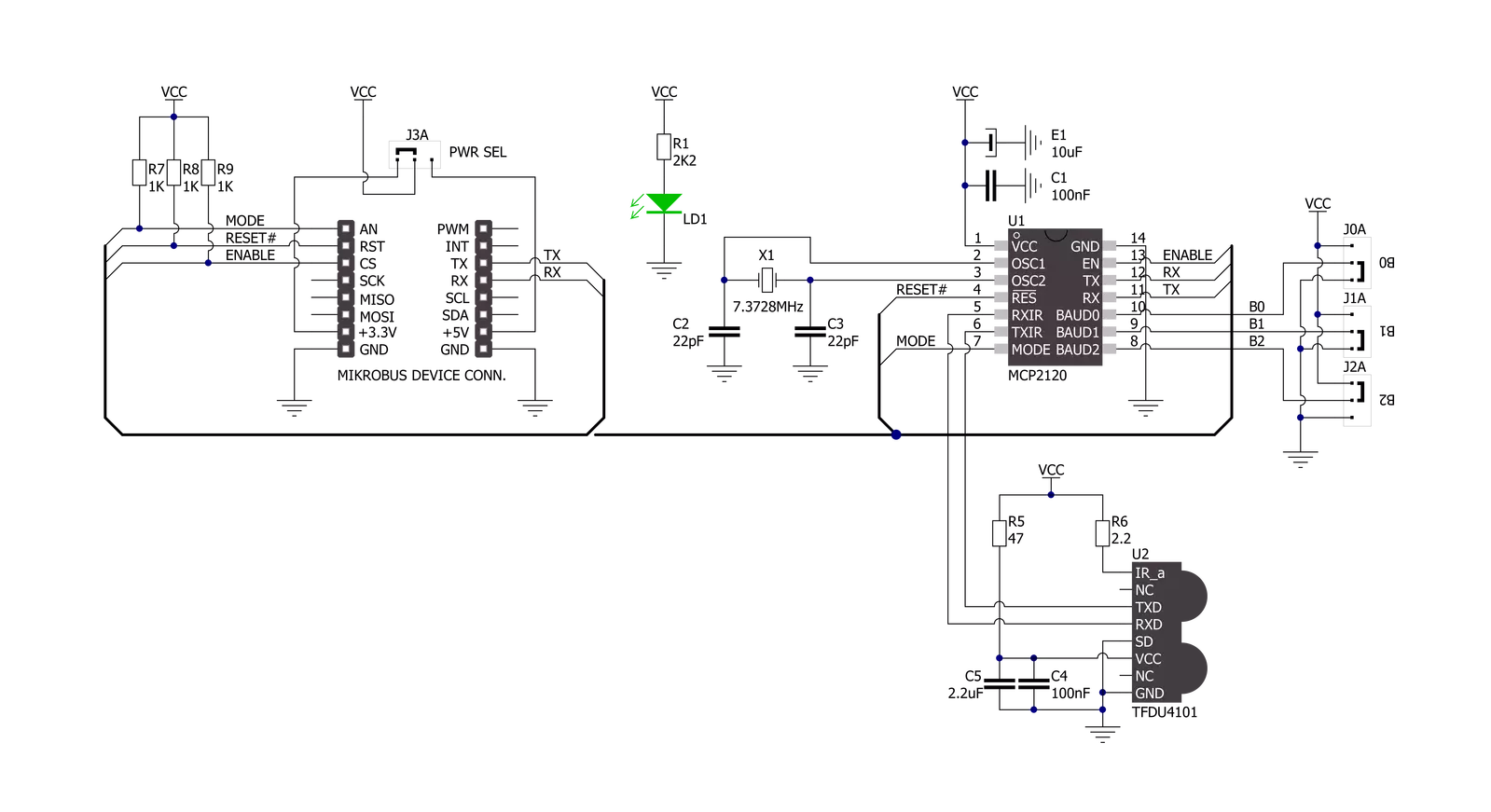
IrDA 2 Click is based on the MCP2120, a high-performance fully-static infrared encoder/decoder from Microchip for sending and receiving IR serial data from the infrared transceiver module, the TFDU4101 from Vishay semiconductor. This way, the MCP2120 adds IR capability to any embedded application with serial data. The data from a standard UART is encoded (modulated) and output as electrical pulses to the IR Transceiver. Besides, the IR Transceiver also receives and outputs electrical pulses, which the MCP2120 decodes (demodulates) and transmits by the UART interface. The latest IrDAR physical layer standard performs this modulation and demodulation method for fast infrared data communication, supporting IrDA speeds up to 115.2kbit/s. Integrated within the TFDU4101 transceiver module is a photo pin diode, an infrared emitter (IRED), and a low-power control
IC to provide a total front-end solution in a single package. This Click board™ covers the full IrDA range of more than 1m and can be turned on or off through the EN pin routed to the CS pin of the mikroBUS™ socket; hence, offering a switch operation to turn ON/OFF power delivery to the MCP2120. The MCP2120 will encode and decode serial data at the selected data or baud rate. The selection can be made by positioning SMD jumpers labeled as BR SEL in an appropriate position marked as 1 or 0. Also, the software baud rate selection is selected if all these jumpers are in a high (1) position. For any other inputs, the hardware select mode is active. This setting is latched when the MCP2120 is reset from the RST pin of the mikroBUS™ socket. After an MCP2120 reset, changing the value of the baud pins does not affect the device’s baud rate. Software baud data
rate is intended for use with systems where switching data rates must be performed frequently between the MCP2120 and the embedded host. In software baud mode, the MCP2120 differentiates between data and commands. This feature is controlled via the MOD pin routed to the AN pin of the mikroBUS™ socket. The MOD pin is used to switch between command and data modes, and when the MOD pin is in a low state, the MCP2120 is in command mode; otherwise, the MCP2120 is in data mode. This Click board™ can operate with either 3.3V or 5V logic voltage levels selected via the PWR SEL jumper. This way, both 3.3V and 5V capable MCUs can use the communication lines properly. Also, this Click board™ comes equipped with a library containing easy-to-use functions and an example code that can be used as a reference for further development.

Features overview
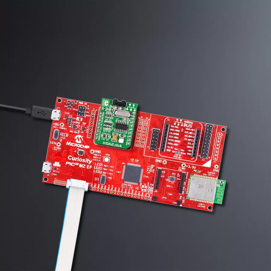
Development board
Curiosity PIC32 MZ EF development board is a fully integrated 32-bit development platform featuring the high-performance PIC32MZ EF Series (PIC32MZ2048EFM) that has a 2MB Flash, 512KB RAM, integrated FPU, Crypto accelerator, and excellent connectivity options. It includes an integrated programmer and debugger, requiring no additional hardware. Users can expand
functionality through MIKROE mikroBUS™ Click™ adapter boards, add Ethernet connectivity with the Microchip PHY daughter board, add WiFi connectivity capability using the Microchip expansions boards, and add audio input and output capability with Microchip audio daughter boards. These boards are fully integrated into PIC32’s powerful software framework, MPLAB Harmony,
which provides a flexible and modular interface to application development a rich set of inter-operable software stacks (TCP-IP, USB), and easy-to-use features. The Curiosity PIC32 MZ EF development board offers expansion capabilities making it an excellent choice for a rapid prototyping board in Connectivity, IOT, and general-purpose applications.

Microcontroller Overview
MCU Card / MCU

Architecture
PIC32
MCU Memory (KB)
2048
Silicon Vendor
Microchip
Pin count
100
RAM (Bytes)
524288
Used MCU Pins
mikroBUS™ mapper
Take a closer look
Click board™ Schematic
Step by step
Project assembly

Start by selecting your development board and Click board™. Begin with the Curiosity PIC32 MZ EF as your development board.


Software Support
Library Description
This library contains API for IrDA 2 Click driver.
Key functions:
irda2_generic_write- This function writes a desired number of data bytes by using UART serial interfaceirda2_generic_read- This function reads a desired number of data bytes by using UART serial interfaceirda2_reset- This function executes a device reset operation
Open Source
Code example
The complete application code and a ready-to-use project are available through the NECTO Studio Package Manager for direct installation in the NECTO Studio. The application code can also be found on the MIKROE GitHub account.
/*!
 * @file main.c
 * @brief IrDA 2 Click Example.
 *
 * # Description
 * This example demonstrates the use of an IrDA 2 Click board by showing
 * the communication between the two Click boards.
 *
 * The demo application is composed of two sections :
 *
 * ## Application Init
 * Initalizes device and makes an initial log.
 *
 * ## Application Task
 * Depending on the selected application mode, it reads all the received data or
 * sends the desired text message once per second.
 *
 * @author MikroE Team
 *
 */
#include "board.h"
#include "log.h"
#include "irda2.h"

// Comment out the line below in order to switch the application mode to receiver
#define DEMO_APP_TRANSMITTER

// Text message to send in the transmitter application mode
#define DEMO_TEXT_MESSAGE           "MIKROE - IrDA 2 Click board\r\n\0"

static irda2_t irda2;
static log_t logger;

void application_init ( void )
{
    irda2_cfg_t irda2_cfg;
    log_cfg_t logger_cfg;

    /**
     * Logger initialization.
     * Default baud rate: 115200
     * Default log level: LOG_LEVEL_DEBUG
     * @note If USB_UART_RX and USB_UART_TX
     * are defined as HAL_PIN_NC, you will
     * need to define them manually for log to work.
     * See @b LOG_MAP_USB_UART macro definition for detailed explanation.
     */
    LOG_MAP_USB_UART( logger_cfg );
    log_init( &logger, &logger_cfg );
    log_info( &logger, " Application Init " );

    //  Click initialization.
    irda2_cfg_setup( &irda2_cfg );
    IRDA2_MAP_MIKROBUS( irda2_cfg, MIKROBUS_1 );
    if ( UART_ERROR == irda2_init( &irda2, &irda2_cfg ) )
    {
        log_error( &logger, " Communication init." );
        for ( ; ; );
    }
    irda2_default_cfg( &irda2 );
    irda2_reset( &irda2 );

#ifdef DEMO_APP_TRANSMITTER
    log_printf( &logger, " Application Mode: Transmitter\r\n" );
#else
    log_printf( &logger, " Application Mode: Receiver\r\n" );
#endif
    log_info( &logger, " Application Task " );
}

void application_task ( void )
{
#ifdef DEMO_APP_TRANSMITTER
    irda2_generic_write( &irda2, DEMO_TEXT_MESSAGE, strlen( DEMO_TEXT_MESSAGE ) );
    log_printf( &logger, "%s", ( char * ) DEMO_TEXT_MESSAGE );
    Delay_ms ( 1000 );
#else
    uint8_t rx_byte = 0;
    if ( 1 == irda2_generic_read( &irda2, &rx_byte, 1 ) )
    {
       log_printf( &logger, "%c", rx_byte );
    }
#endif
}

int main ( void )
{
    /* Do not remove this line or clock might not be set correctly. */
    #ifdef PREINIT_SUPPORTED
    preinit();
    #endif

    application_init( );

    for ( ; ; )
    {
        application_task( );
    }

    return 0;
}


// ------------------------------------------------------------------------ END
Additional Support
Resources
Category:Optical


