Simplify temperature monitoring with DS1825 and PIC32MZ1024EFH064
From chills to thrills, we measure it all!
Published Jun 22, 2023
Click board™
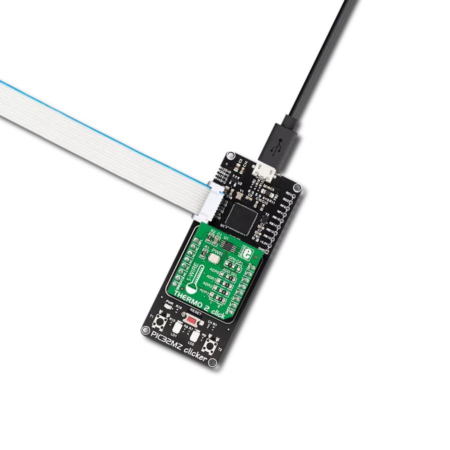
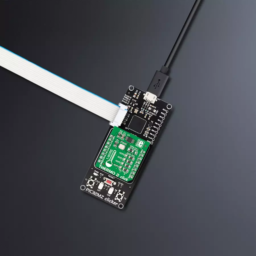
THERMO 2 Click
Dev. board
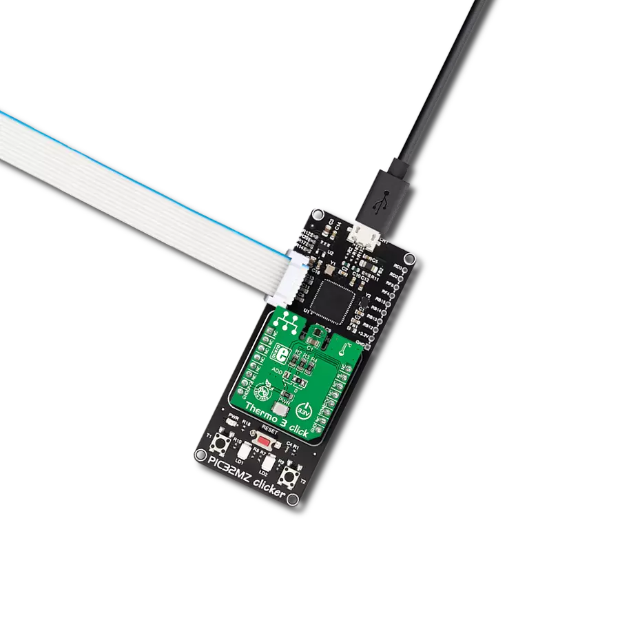
PIC32MZ clicker
Compiler
NECTO Studio
MCU
PIC32MZ1024EFH064
Our temperature measurement solution plays a crucial role in HVAC systems, allowing users to maintain comfortable indoor environments while optimizing energy efficiency
A
A
Hardware Overview
How does it work?
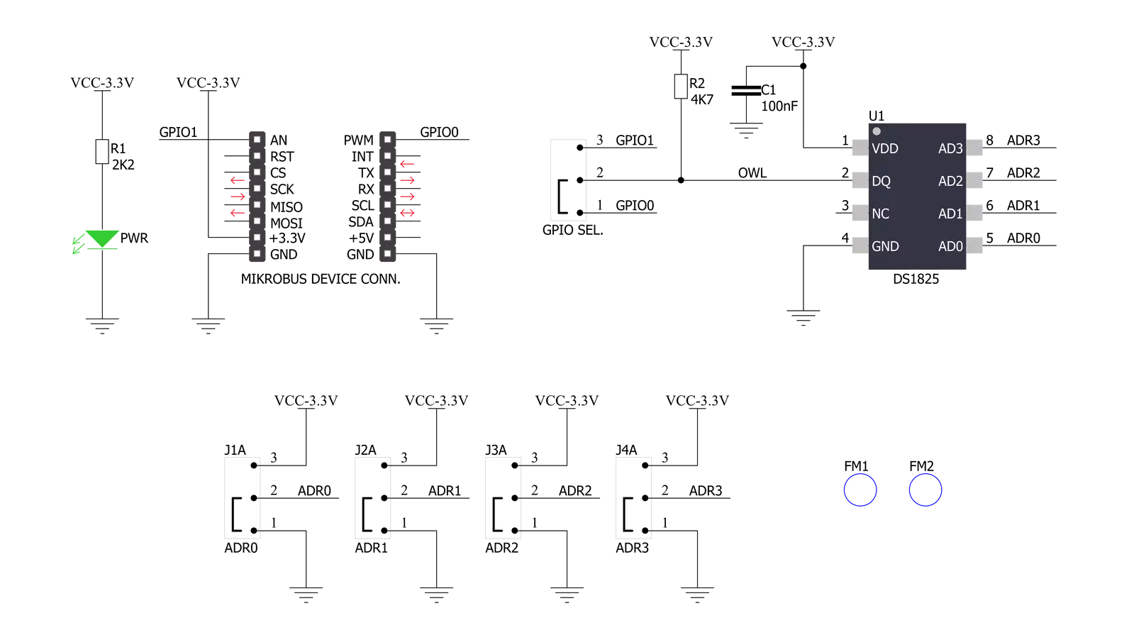
Thermo 2 Click is based on the DS1825, a digital thermometer that provides 9 to 12-bit temperature measurements and communicates over a 1-Wire interface from Analog Devices. The sensor has an extended operating temperature range of -55°C to +125°C, with an accuracy of ±0.5°C over a standard range of -10°C to +85°C, and an alarm function with NV user-programmable upper and lower trigger points. Temperature measurements are sent to the MCU using the 1-Wire interface requiring only one data line that can power the sensor parasitically. A wide span of good qualities makes it ideal for various applications, including HVAC environmental controls, temperature monitoring systems inside buildings,
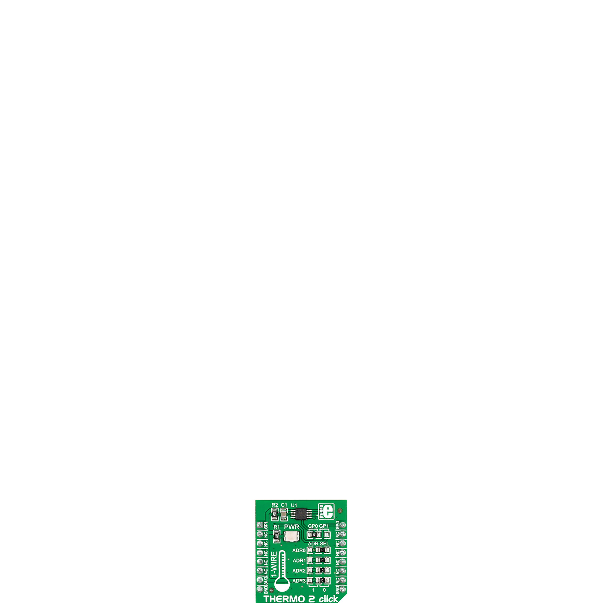
equipment/machinery, and process monitoring and control systems. This Click board™ communicates with MCU using the 1-Wire interface that, by definition, requires only one data line (and ground) for communication with MCU. The 1-Wire communication line is routed to the GP jumper allowing the 1-Wire communication signal to the PWM pin or the AN pin of the mikroBUS™ socket. These pins are labeled GP0 and GP1, respectively, the same as the SMD jumper positions, making selecting the desired pin straightforward. The DS1825 also features four address select jumpers for setting a unique ID for the sensor allowing up to 16 sensors to operate on a single 1-Wire bus. These address pins, ADR0-
ADR3, are programmed by the user and determine the value of the last four LSBs of the I2C address, which can be selected by positioning onboard SMD jumpers labeled as ADR SEL to an appropriate position marked as 1 or 0. This way, the DS1825 provides the opportunity of the 64 possible different location addresses by positioning the SMD jumper to an appropriate position. This Click board™ can be operated only with a 3.3V logic voltage level. The board must perform appropriate logic voltage level conversion before using MCUs with different logic levels. However, the Click board™ comes equipped with a library containing functions and an example code that can be used as a reference for further development.

Features overview
Development board
PIC32MZ Clicker is a compact starter development board that brings the flexibility of add-on Click boards™ to your favorite microcontroller, making it a perfect starter kit for implementing your ideas. It comes with an onboard 32-bit PIC32MZ microcontroller with FPU from Microchip, a USB connector, LED indicators, buttons, a mikroProg connector, and a header for interfacing with external electronics. Thanks to its compact design with clear and easy-recognizable silkscreen markings, it provides a fluid and immersive working experience, allowing access anywhere and under
any circumstances. Each part of the PIC32MZ Clicker development kit contains the components necessary for the most efficient operation of the same board. In addition to the possibility of choosing the PIC32MZ Clicker programming method, using USB HID mikroBootloader, or through an external mikroProg connector for PIC, dsPIC, or PIC32 programmer, the Clicker board also includes a clean and regulated power supply module for the development kit. The USB Micro-B connection can provide up to 500mA of current, which is more than enough to operate all onboard
and additional modules. All communication methods that mikroBUS™ itself supports are on this board, including the well-established mikroBUS™ socket, reset button, and several buttons and LED indicators. PIC32MZ Clicker is an integral part of the Mikroe ecosystem, allowing you to create a new application in minutes. Natively supported by Mikroe software tools, it covers many aspects of prototyping thanks to a considerable number of different Click boards™ (over a thousand boards), the number of which is growing every day.

Microcontroller Overview
MCU Card / MCU

Architecture
PIC32
MCU Memory (KB)
1024
Silicon Vendor
Microchip
Pin count
64
RAM (Bytes)
524288
Used MCU Pins
mikroBUS™ mapper
Take a closer look
Click board™ Schematic
Step by step
Project assembly

Start by selecting your development board and Click board™. Begin with the PIC32MZ clicker as your development board.


Software Support
Library Description
This library contains API for Thermo 2 Click driver.
Key functions:
thermo2_write_scratchpad- This function writes the temperature thresholds and configuration byte to the scratchpad.thermo2_read_scratchpad- This function reads the scratchpad bytes.thermo2_read_temperature- This function reads the temperature value in Celsius.
Open Source
Code example
The complete application code and a ready-to-use project are available through the NECTO Studio Package Manager for direct installation in the NECTO Studio. The application code can also be found on the MIKROE GitHub account.
/*!
 * @file main.c
 * @brief Thermo2 Click example
 *
 * # Description
 * This example demonstrates the use of Thermo 2 Click board by reading
 * and displaying the temperature in Celsius.
 *
 * The demo application is composed of two sections :
 *
 * ## Application Init
 * Initializes the driver and performs the Click default configuration.
 *
 * ## Application Task
 * Reads and displays the temperature measured by the Click board on the USB UART
 * approximately every 800ms as this matches the required conversion time for 12-bit
 * temperature resolution.
 *
 * @author Stefan Filipovic
 *
 */

#include "board.h"
#include "log.h"
#include "thermo2.h"

static thermo2_t thermo2;
static log_t logger;

void application_init ( void )
{
    log_cfg_t log_cfg;  /**< Logger config object. */
    thermo2_cfg_t thermo2_cfg;  /**< Click config object. */

    /**
     * Logger initialization.
     * Default baud rate: 115200
     * Default log level: LOG_LEVEL_DEBUG
     * @note If USB_UART_RX and USB_UART_TX
     * are defined as HAL_PIN_NC, you will
     * need to define them manually for log to work.
     * See @b LOG_MAP_USB_UART macro definition for detailed explanation.
     */
    LOG_MAP_USB_UART( log_cfg );
    log_init( &logger, &log_cfg );
    log_info( &logger, " Application Init " );

    // Click initialization.
    thermo2_cfg_setup( &thermo2_cfg );
    THERMO2_MAP_MIKROBUS( thermo2_cfg, MIKROBUS_1 );
    if ( ONE_WIRE_ERROR == thermo2_init( &thermo2, &thermo2_cfg ) )
    {
        log_error( &logger, " Communication init." );
        for ( ; ; );
    }

    if ( THERMO2_ERROR == thermo2_default_cfg ( &thermo2 ) )
    {
        log_error( &logger, " Default configuration." );
        for ( ; ; );
    }

    log_info( &logger, " Application Task " );
}

void application_task ( void )
{
    float temperature;
    if ( THERMO2_OK == thermo2_read_temperature ( &thermo2, &temperature ) )
    {
        log_printf( &logger, " Temperature: %.2f C\r\n\n", temperature );
    }
}

int main ( void )
{
    /* Do not remove this line or clock might not be set correctly. */
    #ifdef PREINIT_SUPPORTED
    preinit();
    #endif

    application_init( );

    for ( ; ; )
    {
        application_task( );
    }

    return 0;
}

// ------------------------------------------------------------------------ END
Additional Support
Resources
Category:Temperature & humidity