Measure surface temperature without physical contact with the object using the ZTP-148SRC1 and PIC32MZ2048EFM100
Infrared thermopile sensor for non-contact surface temperature measurement

Published Jun 17, 2024
Click board™
IR Sense 5 Click
Dev. board
Curiosity PIC32 MZ EF
Compiler
NECTO Studio
MCU
PIC32MZ2048EFM100
Measure surface temperature within a range of -20 to +100°C without physically touching the object
A
A
Hardware Overview
How does it work?
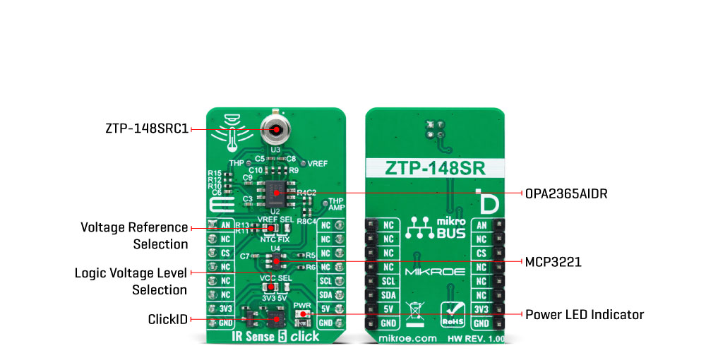
IR Sense 5 Click is based on the ZTP-148SRC1, a thermopile IR sensor from Amphenol. This infrared thermopile sensor is designed for non-contact surface temperature measurement, offering a stable response to DC radiation. The ZTP-148SRC1 can measure temperatures from -20 to +100°C, featuring an active area of 0.7x0.7mm² and a typical field of view (FoV) of 85 degrees. The sensor consists of thermo-elements, a flat IR filter, and a thermistor for temperature compensation, all housed in a hermetically sealed TO package. Its typical applications include human thermometry, non-contact temperature measurement, home appliances such as air conditioners, occupancy detection, HVAC systems, automotive applications, and various other uses. As mentioned, the ZTP-148SRC1 features a high-sensitivity thermopile
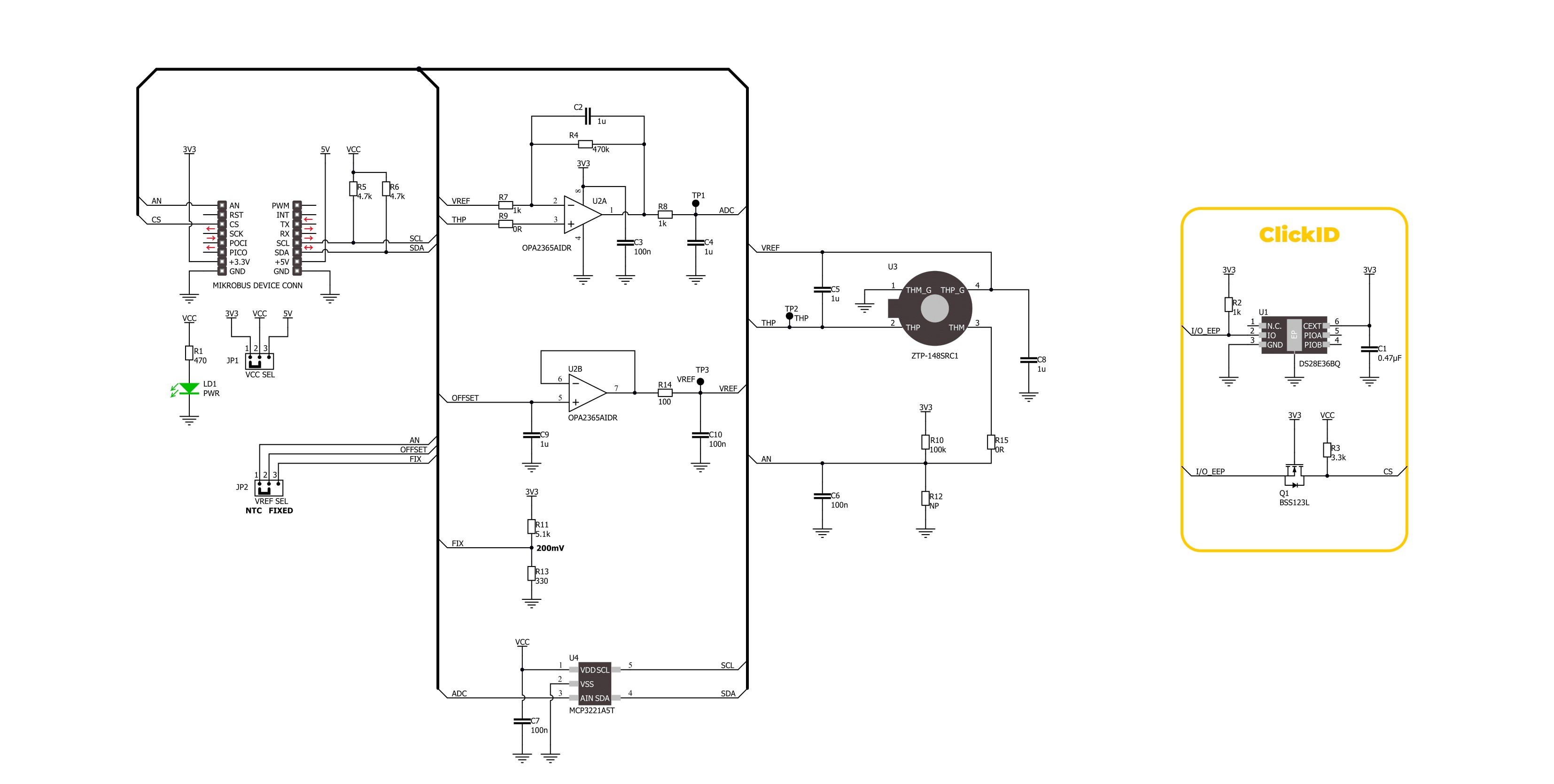
with a rapid response time and an integrated thermistor for precise ambient temperature compensation. As an analog-output sensor, it utilizes the OPA2365AIDR OpAmp to amplify the thermopile's analog output voltage. This amplified signal is then digitized via the I2C interface using the MCP3221 analog-to-digital converter. This board also has an output offset selection achieved via the VREF SEL jumper. Selection is made between a fixed offset value of 200mV, generated by a voltage divider (R11 and R13 resistors) or from the ZTP-148SRC1's thermistor output. This offset is crucial for signal conditioning, ensuring the sensor's output is within the optimal range for further processing and improving measurement accuracy by compensating for ambient temperature variations. Besides, the thermistor's value can be
monitored through the AN pin of the mikroBUS™ socket. The board also includes three test points for signals from the ZTP-148SRC1: the raw signal from the thermopile on TP2, the selected voltage reference at TP3, and the amplified signal from the OPA2365AIDR on TP1. These test points allow consistent prototyping and testing. This Click board™ can operate with either 3.3V or 5V logic voltage levels selected via the VCC SEL jumper. This way, both 3.3V and 5V capable MCUs can use the communication lines properly. Also, this Click board™ comes equipped with a library containing easy-to-use functions and an example code that can be used as a reference for further development.
Features overview
Development board
Curiosity PIC32 MZ EF development board is a fully integrated 32-bit development platform featuring the high-performance PIC32MZ EF Series (PIC32MZ2048EFM) that has a 2MB Flash, 512KB RAM, integrated FPU, Crypto accelerator, and excellent connectivity options. It includes an integrated programmer and debugger, requiring no additional hardware. Users can expand
functionality through MIKROE mikroBUS™ Click™ adapter boards, add Ethernet connectivity with the Microchip PHY daughter board, add WiFi connectivity capability using the Microchip expansions boards, and add audio input and output capability with Microchip audio daughter boards. These boards are fully integrated into PIC32’s powerful software framework, MPLAB Harmony,
which provides a flexible and modular interface to application development a rich set of inter-operable software stacks (TCP-IP, USB), and easy-to-use features. The Curiosity PIC32 MZ EF development board offers expansion capabilities making it an excellent choice for a rapid prototyping board in Connectivity, IOT, and general-purpose applications.

Microcontroller Overview
MCU Card / MCU

Architecture
PIC32
MCU Memory (KB)
2048
Silicon Vendor
Microchip
Pin count
100
RAM (Bytes)
524288
Used MCU Pins
mikroBUS™ mapper
Take a closer look
Click board™ Schematic
Step by step
Project assembly

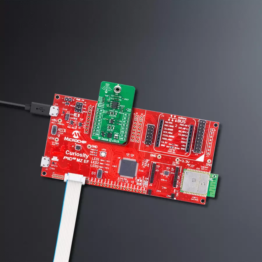
Start by selecting your development board and Click board™. Begin with the Curiosity PIC32 MZ EF as your development board.


Track your results in real time
Application Output
1. Application Output - In Debug mode, the 'Application Output' window enables real-time data monitoring, offering direct insight into execution results. Ensure proper data display by configuring the environment correctly using the provided tutorial.

2. UART Terminal - Use the UART Terminal to monitor data transmission via a USB to UART converter, allowing direct communication between the Click board™ and your development system. Configure the baud rate and other serial settings according to your project's requirements to ensure proper functionality. For step-by-step setup instructions, refer to the provided tutorial.

3. Plot Output - The Plot feature offers a powerful way to visualize real-time sensor data, enabling trend analysis, debugging, and comparison of multiple data points. To set it up correctly, follow the provided tutorial, which includes a step-by-step example of using the Plot feature to display Click board™ readings. To use the Plot feature in your code, use the function: plot(*insert_graph_name*, variable_name);. This is a general format, and it is up to the user to replace 'insert_graph_name' with the actual graph name and 'variable_name' with the parameter to be displayed.

Software Support
Library Description
This library contains API for IR Sense 5 Click driver.
Key functions:
irsense5_get_obj_temp- This function reads and calculate object temperature in degree Celsius [degC].irsense5_get_amb_temp- This function reads and calculate ambient temperature in degree Celsius [degC].irsense5_read_raw_adc_thm- This function reads the thermistor raw ADC value.
Open Source
Code example
The complete application code and a ready-to-use project are available through the NECTO Studio Package Manager for direct installation in the NECTO Studio. The application code can also be found on the MIKROE GitHub account.
/*!
 * @file main.c
 * @brief IR Sense 5 Click Example.
 *
 * # Description
 * This library contains API for the IR Sense 5 Click driver
 * for measuring ambient and object temperature.
 *
 * The demo application is composed of two sections :
 *
 * ## Application Init
 * The initialization of the I2C and ADC module and log UART.
 *
 * ## Application Task
 * The demo application measures ambient and object temperature in degrees Celsius.
 * Results are being sent to the UART Terminal, where you can track their changes.
 *
 * @author Nenad Filipovic
 *
 */

#include "board.h"
#include "log.h"
#include "irsense5.h"

static irsense5_t irsense5;   /**< IR Sense 5 Click driver object. */
static log_t logger;    /**< Logger object. */

void application_init ( void )
{
    log_cfg_t log_cfg;  /**< Logger config object. */
    irsense5_cfg_t irsense5_cfg;  /**< Click config object. */

    /**
     * Logger initialization.
     * Default baud rate: 115200
     * Default log level: LOG_LEVEL_DEBUG
     * @note If USB_UART_RX and USB_UART_TX
     * are defined as HAL_PIN_NC, you will
     * need to define them manually for log to work.
     * See @b LOG_MAP_USB_UART macro definition for detailed explanation.
     */
    LOG_MAP_USB_UART( log_cfg );
    log_init( &logger, &log_cfg );
    log_info( &logger, " Application Init " );

    // Click initialization.
    irsense5_cfg_setup( &irsense5_cfg );
    IRSENSE5_MAP_MIKROBUS( irsense5_cfg, MIKROBUS_1 );
    err_t init_flag = irsense5_init( &irsense5, &irsense5_cfg );
    if ( ( ADC_ERROR == init_flag ) || ( I2C_MASTER_ERROR == init_flag ) )
    {
        log_error( &logger, " Communication init." );
        for ( ; ; );
    }

    log_info( &logger, " Application Task " );
}

void application_task ( void )
{
    float temperature = 0;
    if ( IRSENSE5_OK == irsense5_get_amb_temp ( &irsense5, &temperature ) )
    {
        log_printf( &logger, " Ambient Temperature: %.2f [degC]\r\n", temperature );
        Delay_ms ( 1000 );
    }

    if ( IRSENSE5_OK == irsense5_get_obj_temp ( &irsense5, &temperature ) )
    {
        log_printf( &logger, " Object Temperature:  %.2f [degC]\r\n\n", temperature );
        Delay_ms ( 1000 );
    }
}

int main ( void )
{
    /* Do not remove this line or clock might not be set correctly. */
    #ifdef PREINIT_SUPPORTED
    preinit();
    #endif

    application_init( );

    for ( ; ; )
    {
        application_task( );
    }

    return 0;
}

// ------------------------------------------------------------------------ END


