Create smarter and more interactive digital experiences with ST25DV16K and PIC32MZ1024EFH064
Touch and transform: NFC readers reshaping your digital landscape
Published Oct 18, 2023
Click board™
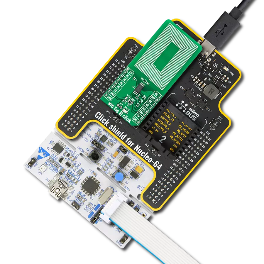
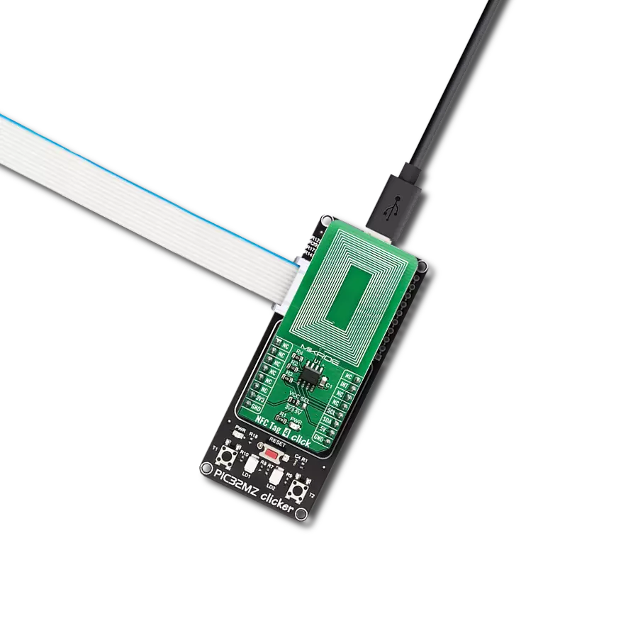
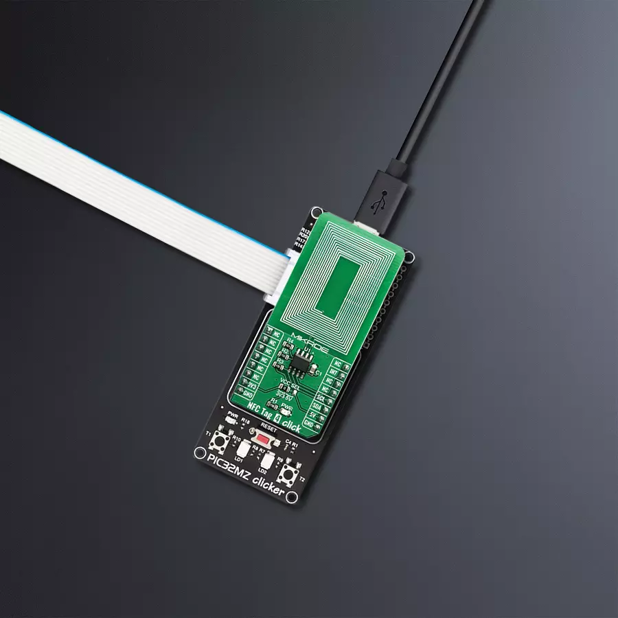
NFC Tag 4 Click
Dev. board
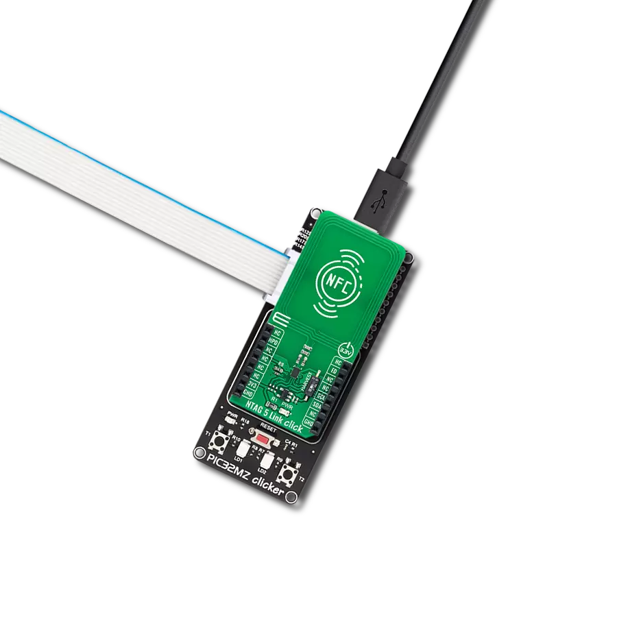
PIC32MZ clicker
Compiler
NECTO Studio
MCU
PIC32MZ1024EFH064
Embrace the NFC experience and see how it extends from simple data sharing to device control, offering a more connected and efficient way of interacting with your digital world
A
A
Hardware Overview
How does it work?
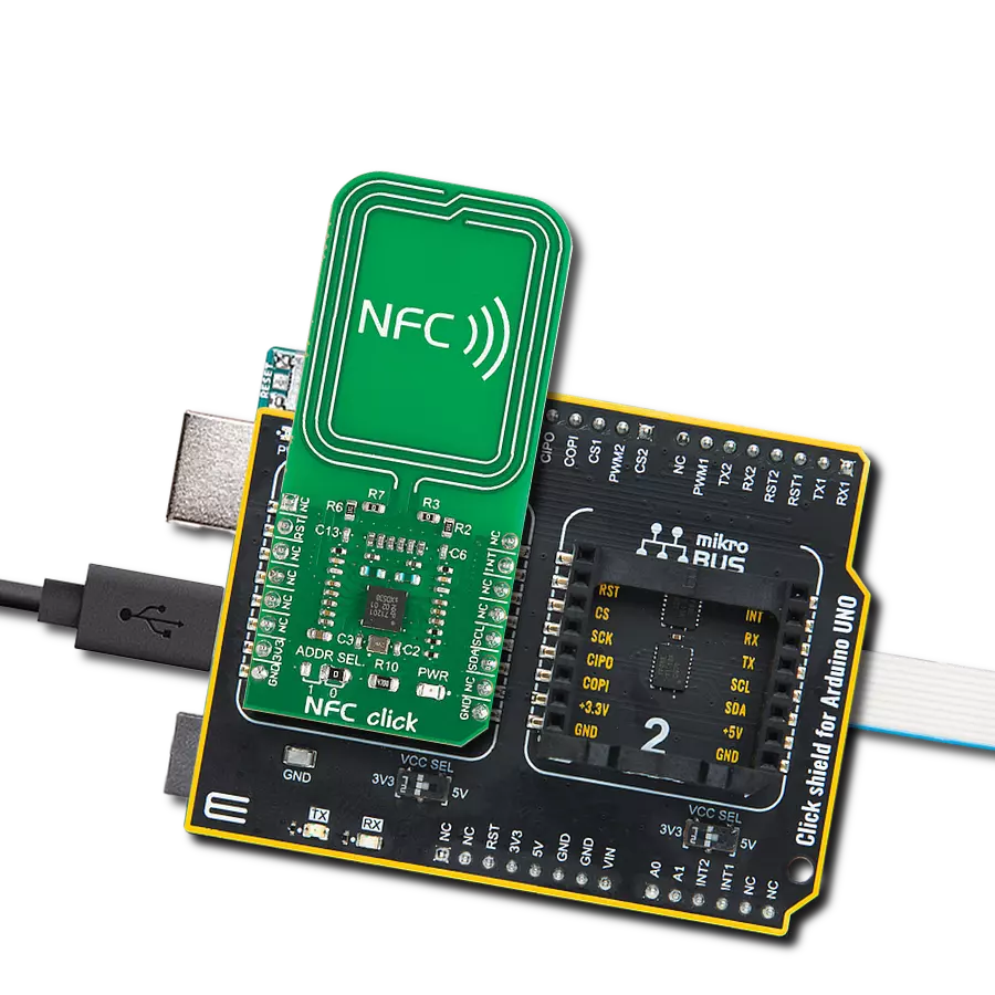
NFC Tag 4 Click is based on the ST25DV16, a compact NFC tag IC from STMicroelectronics. The Click board™ itself has a reasonably small number of components because most of the interface and EEPROM memory circuitry is already integrated on the ST25DV16K IC. The I2C / SMBus compatible serial interface lines, along with the GPO pin, which also works in the open drain configuration, are pulled up by the onboard resistors. The 2-Wire lines are routed to the respective I2C lines of the mikroBUS™ (SCK and SDA), while the GPO pin of the main IC is routed to the INT pin of the mikroBUS™. The ST25DV16K uses the I2C/SMBus compatible communication interface, offering a fast transfer mode (FTM), to achieve a fast link between RF and contact worlds, via a 256 byte buffer called Mailbox. This mailbox dynamic buffer of 256 byte can be filled or emptied via either RF or I2C. There is also the INT pin available, which
indicates incoming event to the contact side, like RF Field changes, RF activity in progress, RF writing completion or Mailbox message availability. The built in energy harvesting element can deliver µW of power when external conditions make it possible. The integrated RF management allows the NFC Tag 4 click to ignore RF requests. All these features can be programmed by setting static and/or dynamic registers of the ST25DV16K. ST25DVxxx can be partially customized using configuration registers located in the E2 system area. More information about all the registers can be found in the ST25DV16K datasheet. However, provided library contains functions that simplify the use of the NFC Tag 4 click. The included application example demonstrates their functionality and it can be used as a reference for custom design. In order to make sure that no external components are required in order to use
it, this Click Board™ contains the integrated trace antenna on the PCB. The antenna coil is correctly tuned and can be used to power and access the device using the ISO/IEC 15693 and ISO 18000-3 mode 1 protocols. Power is transferred to the ST25DV16K by radio frequency at 13.56 MHz via coupling antennas of the NFC Tag 4 click and the NFC Reader being used. The ISO 15693 standard defines the carrier frequency (fC) of the operating field as 13.56 MHz ±7 kHz. This Click board™ can operate with either 3.3V or 5V logic voltage levels selected via the VCC SEL jumper. This way, both 3.3V and 5V capable MCUs can use the communication lines properly. Also, this Click board™ comes equipped with a library containing easy-to-use functions and an example code that can be used as a reference for further development.


Features overview
Development board
PIC32MZ Clicker is a compact starter development board that brings the flexibility of add-on Click boards™ to your favorite microcontroller, making it a perfect starter kit for implementing your ideas. It comes with an onboard 32-bit PIC32MZ microcontroller with FPU from Microchip, a USB connector, LED indicators, buttons, a mikroProg connector, and a header for interfacing with external electronics. Thanks to its compact design with clear and easy-recognizable silkscreen markings, it provides a fluid and immersive working experience, allowing access anywhere and under
any circumstances. Each part of the PIC32MZ Clicker development kit contains the components necessary for the most efficient operation of the same board. In addition to the possibility of choosing the PIC32MZ Clicker programming method, using USB HID mikroBootloader, or through an external mikroProg connector for PIC, dsPIC, or PIC32 programmer, the Clicker board also includes a clean and regulated power supply module for the development kit. The USB Micro-B connection can provide up to 500mA of current, which is more than enough to operate all onboard
and additional modules. All communication methods that mikroBUS™ itself supports are on this board, including the well-established mikroBUS™ socket, reset button, and several buttons and LED indicators. PIC32MZ Clicker is an integral part of the Mikroe ecosystem, allowing you to create a new application in minutes. Natively supported by Mikroe software tools, it covers many aspects of prototyping thanks to a considerable number of different Click boards™ (over a thousand boards), the number of which is growing every day.

Microcontroller Overview
MCU Card / MCU

Architecture
PIC32
MCU Memory (KB)
1024
Silicon Vendor
Microchip
Pin count
64
RAM (Bytes)
524288
Used MCU Pins
mikroBUS™ mapper
Take a closer look
Click board™ Schematic

Step by step
Project assembly

Start by selecting your development board and Click board™. Begin with the PIC32MZ clicker as your development board.


Software Support
Library Description
This library contains API for NFC Tag 4 Click driver.
Key functions:
nfctag4_password_present- This function presents password to device in order to open I2C security sessionnfctag4_enable_mailbox- This function enables or disables mailbox functionalitynfctag4_enable_rf- This function enables or disables RF functionality
Open Source
Code example
The complete application code and a ready-to-use project are available through the NECTO Studio Package Manager for direct installation in the NECTO Studio. The application code can also be found on the MIKROE GitHub account.
/*!
 * \file
 * \brief NfcTag4 Click example
 *
* # Description
 * This example showcases how to configure and use the NFC Tag 4 Click. The Click is an NFC tag
 * interface which uses the I2C serial interface and an RF link interface in order to communicate.
 * The example requires the ST25 NFC Tap application which can be downloaded to your phone.
 *
 * The demo application is composed of two sections :
 *
 * ## Application Init
 * This function initializes and configures the logger and Click modules.
 *
 * ## Application Task
 * This function waits for the interrupt signal, after which it expects data transfers. Once
 * some data has been detected it will open a communication channel with the device transmitting
 * it and show the received data in the UART console.
 *
 * \author MikroE Team
 *
 */
// ------------------------------------------------------------------- INCLUDES

#include "board.h"
#include "log.h"
#include "nfctag4.h"

// ------------------------------------------------------------------ VARIABLES

static nfctag4_t nfctag4;
static log_t logger;

static uint8_t aux_buffer[ 258 ];
static uint16_t i;

static uint16_t message_length = 0;
static transfer_info info;

// ------------------------------------------------------- ADDITIONAL FUNCTIONS

void nfctag4_wait_for_int ()
{
    uint16_t timer_counter = 0;
    uint8_t int_pin_flag = 0;
    int_pin_flag = nfctag4_int_get( &nfctag4 );
    while ( ( int_pin_flag == 1 ) && ( timer_counter <= 300 ) )
    {
        Delay_ms ( 1 );
        timer_counter++;
        int_pin_flag = nfctag4_int_get( &nfctag4 );
    }

    if ( timer_counter <= 300 )
    {
        int_pin_flag = nfctag4_int_get( &nfctag4 );
        while ( int_pin_flag == 0 )
        {
            int_pin_flag = nfctag4_int_get( &nfctag4 );
        }
    }

    timer_counter = 0;
}

// ------------------------------------------------------ APPLICATION FUNCTIONS

void application_init ( void )
{
    log_cfg_t log_cfg;
    nfctag4_cfg_t cfg;

    /**
     * Logger initialization.
     * Default baud rate: 115200
     * Default log level: LOG_LEVEL_DEBUG
     * @note If USB_UART_RX and USB_UART_TX
     * are defined as HAL_PIN_NC, you will
     * need to define them manually for log to work.
     * See @b LOG_MAP_USB_UART macro definition for detailed explanation.
     */
    LOG_MAP_USB_UART( log_cfg );
    log_init( &logger, &log_cfg );
    log_info( &logger, "---- Application Init ----" );

    nfctag4_cfg_setup( &cfg );
    NFCTAG4_MAP_MIKROBUS( cfg, MIKROBUS_1 );
    nfctag4_init( &nfctag4, &cfg );

    nfctag4_default_cfg( &nfctag4 );
}

void application_task ( void )
{
    nfctag4_wait_for_int( );

    info.memory_area = NFCTAG4_MEMORY_DYNAMIC;
    info.register_address = NFCTAG4_DYNAMIC_REG_MB_CTRL;
    info.n_registers = 1;
    nfctag4_i2c_get( &nfctag4, &info, aux_buffer );

    if ( ( aux_buffer[ 0 ] & 0x04 ) == ( 0x04 ) )
    {
        nfctag4_wait_for_int( );
        info.memory_area = NFCTAG4_MEMORY_DYNAMIC;
        info.register_address = NFCTAG4_DYNAMIC_REG_MB_LEN;
        info.n_registers = 1;
        nfctag4_i2c_get( &nfctag4, &info, aux_buffer );
        message_length = aux_buffer[ 0 ];
        message_length++;
        nfctag4_wait_for_int( );
        info.memory_area = NFCTAG4_MEMORY_MAILBOX;
        info.register_address = NFCTAG4_MAILBOX_REG_BYTE_0;
        info.n_registers = message_length;
        nfctag4_i2c_get( &nfctag4, &info, aux_buffer );

        log_printf( &logger, "************* MESSAGE ***************\r\n" );
        log_printf( &logger, " ** Message length:  %u Bytes**\r\n", message_length );

        for ( i = 0; i < message_length; i++ )
        {
            log_printf( &logger, " %u : 0x%x\r\n", i, ( uint16_t ) aux_buffer[ i ] );
        }

        log_printf( &logger, "************** END ****************\r\n" );
    }
}

int main ( void )
{
    /* Do not remove this line or clock might not be set correctly. */
    #ifdef PREINIT_SUPPORTED
    preinit();
    #endif

    application_init( );

    for ( ; ; )
    {
        application_task( );
    }

    return 0;
}


// ------------------------------------------------------------------------ END