Transform magnetic fields into valuable 3D insights with TLI493D-W2BW and PIC32MZ1024EFH064
Your precision partner in magnetic sensing

Published Sep 27, 2023
Click board™
3D Hall 8 Click
Dev. board
PIC32MZ clicker
Compiler
NECTO Studio
MCU
PIC32MZ1024EFH064
Unlock the full potential of 3D magnetic sensing with our cutting-edge technology, revolutionizing industries and enhancing everyday lifestyles
A
A
Hardware Overview
How does it work?
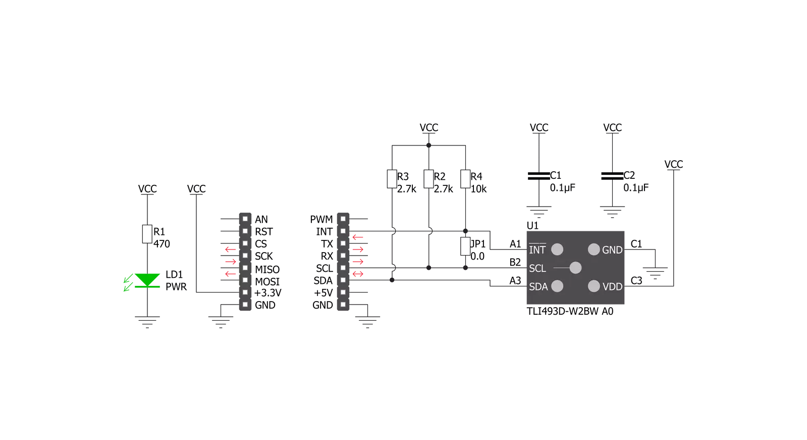
3D Hall 8 Click is based on the TLI493D-W2BW, a low-power 3D Hall sensor with an I2C interface and a Wake-Up feature from Infineon. It consists of three central functional units containing the power mode control system, a low-power oscillator, basic biasing, undervoltage detection, and a fast oscillator. Besides, it has also implemented the sensing unit, which contains the HALL biasing, HALL probes with multiplexers and successive tracking ADC, and a temperature sensor. This sensor offers several use cases, including innovative human-machine interfaces in the form of industrial and consumer joysticks and precise position control in robotics. The power mode control provides the power distribution, which manages the Start-Up behavior in the TLI493D-W2BW, a power-on reset function, and a specialized low-power oscillator, the clock source.
The sensing unit measures the magnetic field in the X, Y, and Z directions. Each X-, Y-, and Z-Hall probe is connected sequentially to a multiplexer, connected to an analog-to-digital converter. Optional, the temperature measurement feature, activated in the default state, can be determined after the three Hall channels. 3D Hall 8 Click communicates with MCU using the standard I2C 2-Wire interface to read data and configure settings, supporting Fast Mode operation with a clock frequency up to 1MHz. The Wake-Up function has an upper and lower comparison threshold for each of the three magnetic channels (X/Y/Z). Each component of the applied field is compared to the lower and upper thresholds. If one of the results is above or below these thresholds, an interrupt is generated called a Wake-Up function. The Wake-Up mode allows the
sensor to continue making magnetic field measurements while the MCU is in the power-down state, which means the microcontroller will only consume power and access the sensor if relevant measurement data is available. An interrupt pin signals a finished measurement cycle but can also be used for I2C clock stretching. In this case, the INT pin must be connected to the SCL pin, which can be done by populating the jumper labeled JP1. This Click board™ can be operated only with a 3.3V logic voltage level. The board must perform appropriate logic voltage level conversion before using MCUs with different logic levels. Also, it comes equipped with a library containing functions and an example code that can be used as a reference for further development.


Features overview
Development board
PIC32MZ Clicker is a compact starter development board that brings the flexibility of add-on Click boards™ to your favorite microcontroller, making it a perfect starter kit for implementing your ideas. It comes with an onboard 32-bit PIC32MZ microcontroller with FPU from Microchip, a USB connector, LED indicators, buttons, a mikroProg connector, and a header for interfacing with external electronics. Thanks to its compact design with clear and easy-recognizable silkscreen markings, it provides a fluid and immersive working experience, allowing access anywhere and under
any circumstances. Each part of the PIC32MZ Clicker development kit contains the components necessary for the most efficient operation of the same board. In addition to the possibility of choosing the PIC32MZ Clicker programming method, using USB HID mikroBootloader, or through an external mikroProg connector for PIC, dsPIC, or PIC32 programmer, the Clicker board also includes a clean and regulated power supply module for the development kit. The USB Micro-B connection can provide up to 500mA of current, which is more than enough to operate all onboard
and additional modules. All communication methods that mikroBUS™ itself supports are on this board, including the well-established mikroBUS™ socket, reset button, and several buttons and LED indicators. PIC32MZ Clicker is an integral part of the Mikroe ecosystem, allowing you to create a new application in minutes. Natively supported by Mikroe software tools, it covers many aspects of prototyping thanks to a considerable number of different Click boards™ (over a thousand boards), the number of which is growing every day.

Microcontroller Overview
MCU Card / MCU

Architecture
PIC32
MCU Memory (KB)
1024
Silicon Vendor
Microchip
Pin count
64
RAM (Bytes)
524288
Used MCU Pins
mikroBUS™ mapper
Take a closer look
Click board™ Schematic
Step by step
Project assembly

Start by selecting your development board and Click board™. Begin with the PIC32MZ clicker as your development board.


Software Support
Library Description
This library contains API for 3D Hall 8 Click driver.
Key functions:
c3dhall8_generic_write- 3D Hall 8 I2C writing functionc3dhall8_read_sensor_data- Reading sensor data functionc3dhall8_get_xyz_magnetic_matching- Calculating magnetic matching
Open Source
Code example
The complete application code and a ready-to-use project are available through the NECTO Studio Package Manager for direct installation in the NECTO Studio. The application code can also be found on the MIKROE GitHub account.
/*!
 * @file main.c
 * @brief 3DHall8 Click example
 *
 * # Description
 * This application shows capability of 3D Hall 8 Click board.
 * It configures device and reads sensor data. Sensor is capeable
 * of reading magnetic flux density from 3 axes and temperature.
 *
 * The demo application is composed of two sections :
 *
 * ## Application Init
 * Initialization of device communication and application log
 * and configures device.
 *
 * ## Application Task
 * Reads data from the device and logs it in span of 500ms.
 *
 * @author Luka Filipovic
 *
 */

#include "board.h"
#include "log.h"
#include "c3dhall8.h"

static c3dhall8_t c3dhall8;
static log_t logger;

void application_init ( void )
{
    log_cfg_t log_cfg;  /**< Logger config object. */
    c3dhall8_cfg_t c3dhall8_cfg;  /**< Click config object. */
    uint8_t rx_data;

    /**
     * Logger initialization.
     * Default baud rate: 115200
     * Default log level: LOG_LEVEL_DEBUG
     * @note If USB_UART_RX and USB_UART_TX
     * are defined as HAL_PIN_NC, you will
     * need to define them manually for log to work.
     * See @b LOG_MAP_USB_UART macro definition for detailed explanation.
     */
    LOG_MAP_USB_UART( log_cfg );
    log_init( &logger, &log_cfg );
    log_info( &logger, " Application Init " );

    // Click initialization.

    c3dhall8_cfg_setup( &c3dhall8_cfg );
    C3DHALL8_MAP_MIKROBUS( c3dhall8_cfg, MIKROBUS_1 );
    err_t init_flag = c3dhall8_init( &c3dhall8, &c3dhall8_cfg );
    if ( init_flag == I2C_MASTER_ERROR )
    {
        log_error( &logger, " Application Init Error. " );
        log_info( &logger, " Please, run program again... " );

        for ( ; ; );
    }

    log_printf( &logger," > Setting configuration...\r\n" );
    c3dhall8_default_cfg ( &c3dhall8 );

    log_info( &logger, " Application Task " );
    log_printf( &logger, "**************************************\r\n" );
    Delay_ms ( 1000 );
}

void application_task ( void )
{
    c3dhall8_data_t sens_data;
    c3dhall8_read_sensor_data( &c3dhall8, &sens_data );

    log_printf( &logger, "> X[mT]: %.2f\r\n> Y[mT]: %.2f\r\n> Z[mT]: %.2f \r\n> Temperature[C]: %.2f\r\n",
                sens_data.x_axis, sens_data.y_axis, sens_data.z_axis, sens_data.temperature );
    float magnetic_match = c3dhall8_get_xyz_magnetic_matching( &c3dhall8, sens_data );
    log_printf( &logger, "> XYZ magnetic matching: %.2f\r\n", magnetic_match );
    log_printf( &logger, "**************************************\r\n" );

    Delay_ms ( 500 );
}

int main ( void )
{
    /* Do not remove this line or clock might not be set correctly. */
    #ifdef PREINIT_SUPPORTED
    preinit();
    #endif

    application_init( );

    for ( ; ; )
    {
        application_task( );
    }

    return 0;
}

// ------------------------------------------------------------------------ END
Additional Support
Resources
Category:Magnetic


