Know the exact position of your solution with MK64FN1M0VDC12 and A2200-A
Navigating life's routes with unmatched GPS precision

Published Sep 02, 2023
Click board™
GPS 6 Click
Dev. board
Clicker 2 for Kinetis
Compiler
NECTO Studio
MCU
MK64FN1M0VDC12
Explore new horizons, blaze trails, and experience the outdoors with the assurance that your journey is enhanced by exceptional GPS accuracy
A
A
Hardware Overview
How does it work?
GPS 6 Click is based on the A2200-A, a high-performance Global Positioning System (GPS) module from Lantronix. This GPS module enables fast acquisition and tracking built on the SiRFstar IV technology. It operates with a frequency of 1,575GHz with accuracy from 2 to 2.5m and fully addresses the demand for the lowest power consumption. It is characterized by a high sensitivity of -148dBm during acquisition or while tracking (navigation sensitivity of -160dBm and tracking sensitivity of -163dBm) besides removing jammers during acquisition, allowing usage in many different environments and under harsh operating conditions. This Click board™ is configured in the Self-Start mode of operation by ON_OFF and WAKEUP pins connected. The entire
power operation will be activated in Self-Start mode once the 3V3 power rail is applied. The A2200-A communicates with the MCU using the UART interface with commonly used UART RX and TX pins as its communication protocol, operating at 115200bps by default to transmit and exchange data with the host MCU. It also possesses an active-low reset signal routed on the RST pin of the mikroBUS™ socket that activates a hardware reset of the A2200-A. On this line, the MAX809 is also connected, which performs a single function; it asserts a reset signal whenever the 3V3 supply voltage declines below a preset threshold. In addition to precise positioning, GPS allows for accurate timing due to the synchronized atomic clocks in the GPS satellites. While the current date
and time are transmitted in NMEA sentences (UTC), a precise and accurate timing signal is provided via the 1PPS pin of the A2200 GPS receiver and indicated via a red LED indicator marked as PPS. GPS 6 Click possesses the SMA antenna connector with an impedance of 50Ω, which can connect the appropriate passive antenna that MIKROE offers for improved range and received signal strength. This Click board™ can be operated only with a 3.3V logic voltage level. The board must perform appropriate logic voltage level conversion before using MCUs with different logic levels. Also, it comes equipped with a library containing functions and an example code that can be used as a reference for further development.


Features overview
Development board
Clicker 2 for Kinetis is a compact starter development board that brings the flexibility of add-on Click boards™ to your favorite microcontroller, making it a perfect starter kit for implementing your ideas. It comes with an onboard 32-bit ARM Cortex-M4F microcontroller, the MK64FN1M0VDC12 from NXP Semiconductors, two mikroBUS™ sockets for Click board™ connectivity, a USB connector, LED indicators, buttons, a JTAG programmer connector, and two 26-pin headers for interfacing with external electronics. Its compact design with clear and easily recognizable silkscreen markings allows you to build gadgets with unique functionalities and
features quickly. Each part of the Clicker 2 for Kinetis development kit contains the components necessary for the most efficient operation of the same board. In addition to the possibility of choosing the Clicker 2 for Kinetis programming method, using a USB HID mikroBootloader or an external mikroProg connector for Kinetis programmer, the Clicker 2 board also includes a clean and regulated power supply module for the development kit. It provides two ways of board-powering; through the USB Micro-B cable, where onboard voltage regulators provide the appropriate voltage levels to each component on the board, or
using a Li-Polymer battery via an onboard battery connector. All communication methods that mikroBUS™ itself supports are on this board, including the well-established mikroBUS™ socket, reset button, and several user-configurable buttons and LED indicators. Clicker 2 for Kinetis is an integral part of the Mikroe ecosystem, allowing you to create a new application in minutes. Natively supported by Mikroe software tools, it covers many aspects of prototyping thanks to a considerable number of different Click boards™ (over a thousand boards), the number of which is growing every day.

Microcontroller Overview
MCU Card / MCU

Architecture
ARM Cortex-M4
MCU Memory (KB)
1024
Silicon Vendor
NXP
Pin count
121
RAM (Bytes)
262144
You complete me!
Accessories
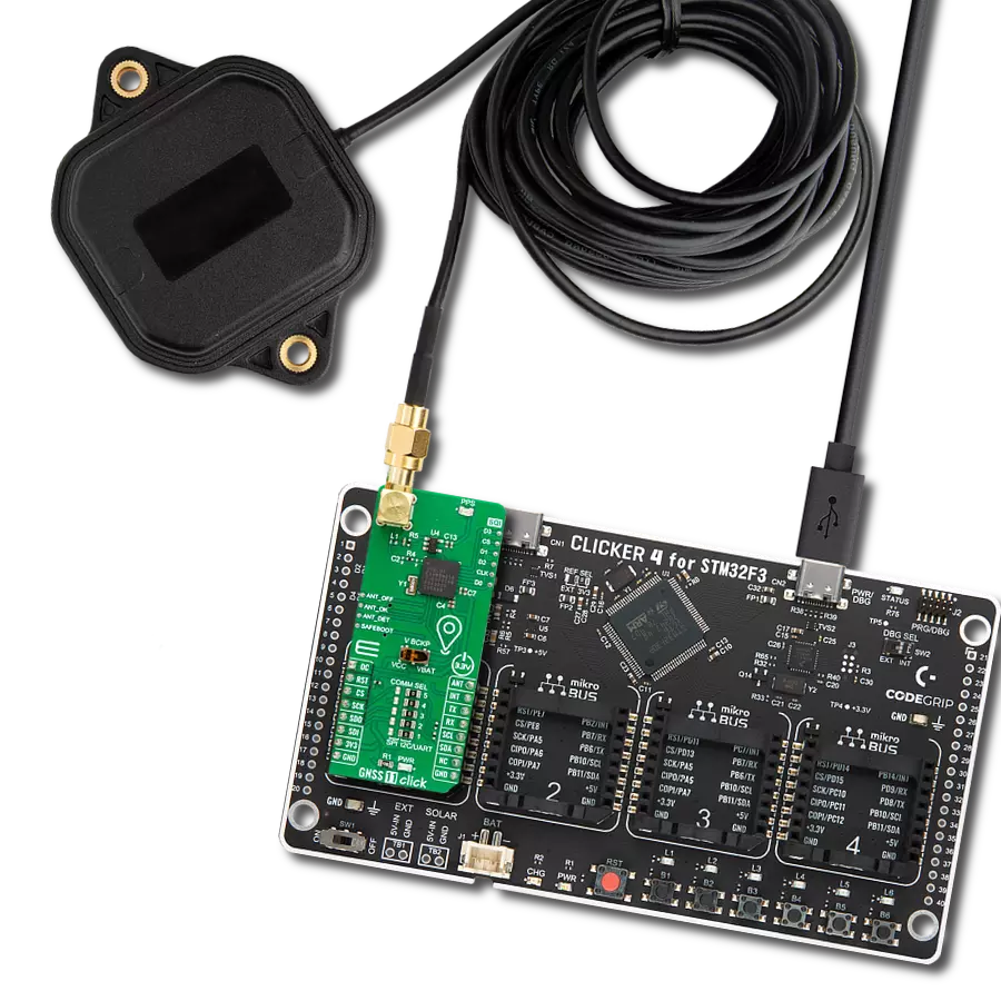
GPS/3G External Antenna is an ideal choice for our GPS/GSM/3G Click boards™. It excels in providing strong GSM and 3G signal reception alongside impressive GPS positioning capabilities. Its robust design features a screw mount and adhesive base, ensuring secure attachment and optimal performance. This antenna boasts separate lines for GPS, GSM, and 3G, making it a versatile choice for applications that demand reliable communication and precise positioning. With a broad frequency range covering 850/900/1800/1900/2100MHz and 50Ω impedance, this antenna guarantees connectivity across various network bands. Its VSW Ratio of 2:1 and peak gain ranging from 1 to 1.5dBic (dependent on frequency) further enhance signal strength. The antenna offers a bandwidth exceeding 10MHz, ensuring consistent reception, while its linear polarization and omnidirectional azimuth coverage provide comprehensive signal accessibility.

Used MCU Pins
mikroBUS™ mapper
Take a closer look
Click board™ Schematic

Step by step
Project assembly

Start by selecting your development board and Click board™. Begin with the Clicker 2 for Kinetis as your development board.


Track your results in real time
Application Output
1. Application Output - In Debug mode, the 'Application Output' window enables real-time data monitoring, offering direct insight into execution results. Ensure proper data display by configuring the environment correctly using the provided tutorial.

2. UART Terminal - Use the UART Terminal to monitor data transmission via a USB to UART converter, allowing direct communication between the Click board™ and your development system. Configure the baud rate and other serial settings according to your project's requirements to ensure proper functionality. For step-by-step setup instructions, refer to the provided tutorial.

3. Plot Output - The Plot feature offers a powerful way to visualize real-time sensor data, enabling trend analysis, debugging, and comparison of multiple data points. To set it up correctly, follow the provided tutorial, which includes a step-by-step example of using the Plot feature to display Click board™ readings. To use the Plot feature in your code, use the function: plot(*insert_graph_name*, variable_name);. This is a general format, and it is up to the user to replace 'insert_graph_name' with the actual graph name and 'variable_name' with the parameter to be displayed.

Software Support
Library Description
This library contains API for GPS 6 Click driver.
Key functions:
gps6_enable_device- This function enables device by setting the RST pin to LOW logic stategps6_generic_read- This function reads a desired number of data bytes by using UART serial interfacegps6_parse_gpgga- This function parses the GPGGA data from the read response buffer
Open Source
Code example
The complete application code and a ready-to-use project are available through the NECTO Studio Package Manager for direct installation in the NECTO Studio. The application code can also be found on the MIKROE GitHub account.
/*!
 * @file main.c
 * @brief GPS 6 Click Example.
 *
 * # Description
 * This example demonstrates the use of GPS 6 Click by reading and displaying
 * the GPS coordinates.
 *
 * The demo application is composed of two sections :
 *
 * ## Application Init
 * Initializes the driver and logger and enables the Click board.
 *
 * ## Application Task
 * Reads the received data, parses the GPGGA info from it, and once it receives the position fix
 * it will start displaying the coordinates on the USB UART.
 *
 * ## Additional Function
 * - static void gps6_clear_app_buf ( void )
 * - static err_t gps6_process ( gps6_t *ctx )
 * - static void gps6_parser_application ( char *rsp )
 *
 * @author Stefan Filipovic
 *
 */

#include "board.h"
#include "log.h"
#include "gps6.h"

#define PROCESS_BUFFER_SIZE 200

static gps6_t gps6;
static log_t logger;

static char app_buf[ PROCESS_BUFFER_SIZE ] = { 0 };
static int32_t app_buf_len = 0;
static int32_t app_buf_cnt = 0;

/**
 * @brief GPS 6 clearing application buffer.
 * @details This function clears memory of application buffer and reset its length and counter.
 * @return None.
 * @note None.
 */
static void gps6_clear_app_buf ( void );

/**
 * @brief GPS 6 data reading function.
 * @details This function reads data from device and concatenates data to application buffer.
 * @param[in] ctx : Click context object.
 * See #gps6_t object definition for detailed explanation.
 * @return @li @c  0 - Read some data.
 *         @li @c -1 - Nothing is read or Application buffer overflow.
 * See #err_t definition for detailed explanation.
 * @note None.
 */
static err_t gps6_process ( gps6_t *ctx );

/**
 * @brief GPS 6 parser application.
 * @param[in] rsp Response buffer.
 * @details This function logs GNSS data on the USB UART.
 * @return None.
 * @note None.
 */
static void gps6_parser_application ( char *rsp );

void application_init ( void )
{
    log_cfg_t log_cfg;  /**< Logger config object. */
    gps6_cfg_t gps6_cfg;  /**< Click config object. */

    /**
     * Logger initialization.
     * Default baud rate: 115200
     * Default log level: LOG_LEVEL_DEBUG
     * @note If USB_UART_RX and USB_UART_TX
     * are defined as HAL_PIN_NC, you will
     * need to define them manually for log to work.
     * See @b LOG_MAP_USB_UART macro definition for detailed explanation.
     */
    LOG_MAP_USB_UART( log_cfg );
    log_init( &logger, &log_cfg );
    log_info( &logger, " Application Init " );

    // Click initialization.
    gps6_cfg_setup( &gps6_cfg );
    GPS6_MAP_MIKROBUS( gps6_cfg, MIKROBUS_1 );
    if ( UART_ERROR == gps6_init( &gps6, &gps6_cfg ) )
    {
        log_error( &logger, " Communication init." );
        for ( ; ; );
    }
    log_info( &logger, " Application Task " );
}

void application_task ( void )
{
    gps6_process( &gps6 );
    if ( app_buf_len > ( sizeof ( ( char * ) GPS6_RSP_GPGGA ) + GPS6_GPGGA_ELEMENT_SIZE ) )
    {
        gps6_parser_application( app_buf );
    }
}

int main ( void )
{
    /* Do not remove this line or clock might not be set correctly. */
    #ifdef PREINIT_SUPPORTED
    preinit();
    #endif

    application_init( );

    for ( ; ; )
    {
        application_task( );
    }

    return 0;
}

static void gps6_clear_app_buf ( void )
{
    memset( app_buf, 0, app_buf_len );
    app_buf_len = 0;
    app_buf_cnt = 0;
}

static err_t gps6_process ( gps6_t *ctx )
{
    int32_t rx_size = 0;
    char rx_buf[ PROCESS_BUFFER_SIZE ] = { 0 };
    rx_size = gps6_generic_read( ctx, rx_buf, PROCESS_BUFFER_SIZE );
    if ( rx_size > 0 )
    {
        int32_t buf_cnt = 0;
        if ( app_buf_len + rx_size >= PROCESS_BUFFER_SIZE )
        {
            gps6_clear_app_buf(  );
            return GPS6_ERROR;
        }
        else
        {
            buf_cnt = app_buf_len;
            app_buf_len += rx_size;
        }
        for ( int32_t rx_cnt = 0; rx_cnt < rx_size; rx_cnt++ )
        {
            if ( rx_buf[ rx_cnt ] )
            {
                app_buf[ ( buf_cnt + rx_cnt ) ] = rx_buf[ rx_cnt ];
            }
            else
            {
                app_buf_len--;
                buf_cnt--;
            }
        }
        return GPS6_OK;
    }
    return GPS6_ERROR;
}

static void gps6_parser_application ( char *rsp )
{
    char element_buf[ 100 ] = { 0 };
    if ( GPS6_OK == gps6_parse_gpgga( rsp, GPS6_GPGGA_LATITUDE, element_buf ) )
    {
        static uint8_t wait_for_fix_cnt = 0;
        if ( strlen( element_buf ) > 0 )
        {
            log_printf( &logger, "\r\n Latitude: %.2s degrees, %s minutes \r\n", element_buf, &element_buf[ 2 ] );
            gps6_parse_gpgga( rsp, GPS6_GPGGA_LONGITUDE, element_buf );
            log_printf( &logger, " Longitude: %.3s degrees, %s minutes \r\n", element_buf, &element_buf[ 3 ] );
            memset( element_buf, 0, sizeof( element_buf ) );
            gps6_parse_gpgga( rsp, GPS6_GPGGA_ALTITUDE, element_buf );
            log_printf( &logger, " Altitude: %s m \r\n", element_buf );
            wait_for_fix_cnt = 0;
        }
        else
        {
            if ( wait_for_fix_cnt % 5 == 0 )
            {
                log_printf( &logger, " Waiting for the position fix...\r\n\n" );
                wait_for_fix_cnt = 0;
            }
            wait_for_fix_cnt++;
        }
        gps6_clear_app_buf(  );
    }
}

// ------------------------------------------------------------------------ END