Achieve precise touch detection from human presence to specific interactions using AS8579 and MK64FN1M0VDC12
Capacitive sensing: Where touch unlocks possibilities!

Published Nov 11, 2023
Click board™
HOD CAP Click
Dev. board
Clicker 2 for Kinetis
Compiler
NECTO Studio
MCU
MK64FN1M0VDC12
The purpose of our capacitive sensor is clear: redefine touch detection with sensitivity and intelligence. From recognizing a human presence to distinguishing specific touch patterns like steering wheel contact, our solution adds a layer of sophistication to your applications.
A
A
Hardware Overview
How does it work?
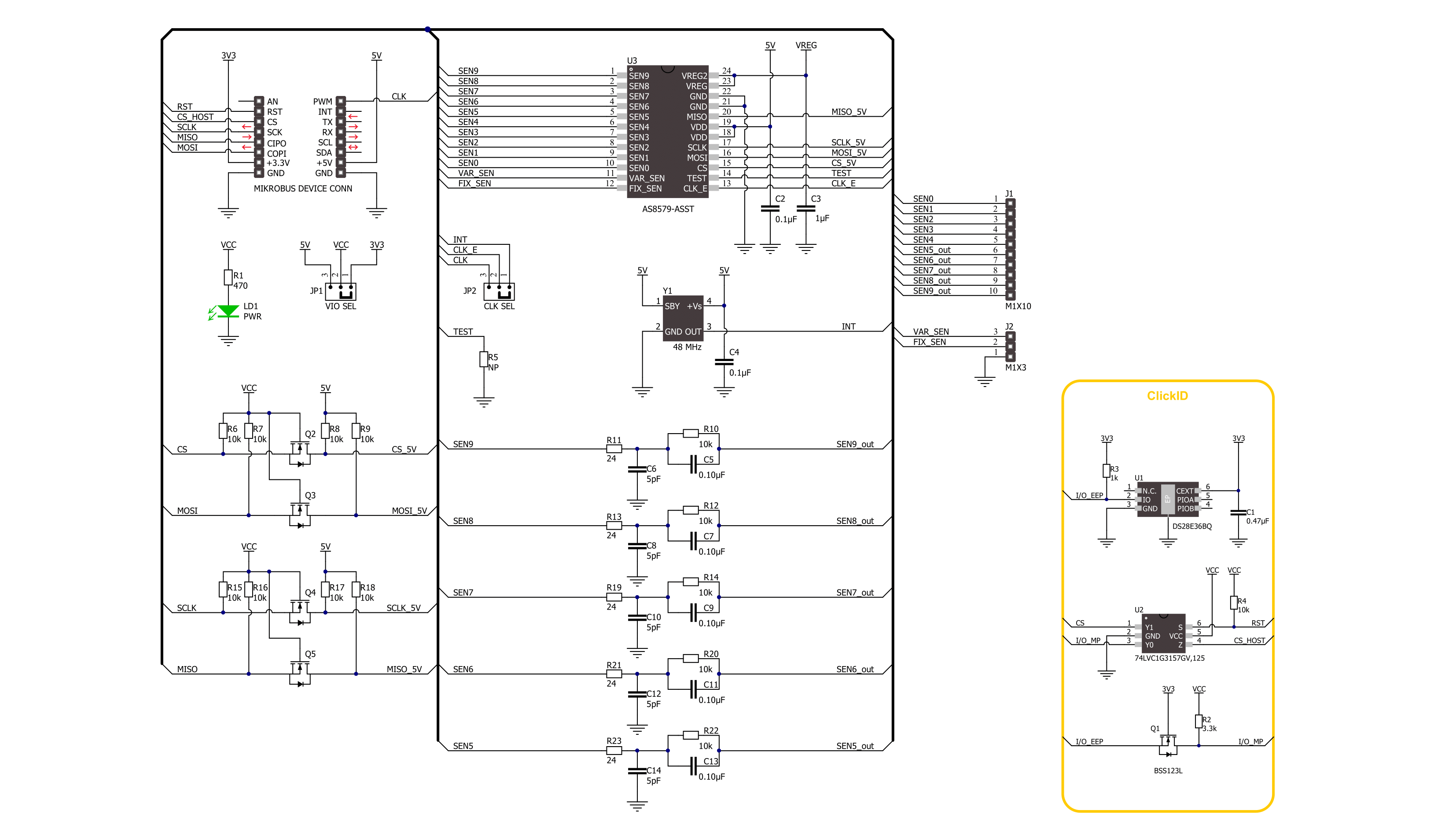
HOD CAP Click is based on the AS8579, a capacitive sensor from ams OSRAM. The AS8579 is a sensor that detects the change of capacity in different applications, as it measures the relative change of the impedance, which can be used for human being detection besides other usages. The sensors' primary function is the transceiver Analog Front-End (AFE) architecture. The AFE function senses the impedance of the output load by using transmitter and receiver blocks. The transmitter block supplies a sine wave across the load, which the receiver blocks capture. The current change is sensed, and the response is converted to a voltage and then demodulated into in-phase (I) and quadrature (Q) components. These I and Q components are later filtered and converted by a 10-bit ADC to digital words. The HOD CAP Click comes with a 10-pin header for sense
outputs labeled SEN0-9. Five of the ten output pins (SEN5-9) are additionally filtered by the SEN Line Filter circuits. Depending on the task, you can set the on-chip ADC in a Single or Continuous Conversion. The first causes the ADC to wait for the system settling time before starting sampling, while the latter causes the ADC to take successive sample accumulations. You can use the CLK SEL jumper to provide the system clock with a frequency in two ways. The selected option INT uses the internal PWM duty cycle of the host MCU to provide a desired frequency, which can be in the range of 3 up to 50MHz. The other option uses onboard 48MHz crystal. In addition, the AS8579 comes with parasitic capacitance protection. A header consisting of VAR SEN, FIX SEN, and GND pins can be used for that purpose. The VAR SEN is a cable shielding driver and should be connected
to a cable shielding to avoid parasitic capacitance influence from shielding. The FIX SEN should be connected to a PCB shield layer to avoid parasitic capacitance influences from the PCB shield layer. Otherwise, both should be connected to the GND. For the factory testing option, you can short the R5. The HOD CAP Click uses the standard 4-Wire SPI serial interface to communicate with the host MCU with a clock frequency of up to 8MHz. This Click board™ can operate with either 3.3V or 5V logic voltage levels selected via the VIO SEL jumper. This way, both 3.3V and 5V capable MCUs can use the communication lines properly. Also, this Click board™ comes equipped with a library containing easy-to-use functions and an example code that can be used as a reference for further development.

Features overview
Development board
Clicker 2 for Kinetis is a compact starter development board that brings the flexibility of add-on Click boards™ to your favorite microcontroller, making it a perfect starter kit for implementing your ideas. It comes with an onboard 32-bit ARM Cortex-M4F microcontroller, the MK64FN1M0VDC12 from NXP Semiconductors, two mikroBUS™ sockets for Click board™ connectivity, a USB connector, LED indicators, buttons, a JTAG programmer connector, and two 26-pin headers for interfacing with external electronics. Its compact design with clear and easily recognizable silkscreen markings allows you to build gadgets with unique functionalities and
features quickly. Each part of the Clicker 2 for Kinetis development kit contains the components necessary for the most efficient operation of the same board. In addition to the possibility of choosing the Clicker 2 for Kinetis programming method, using a USB HID mikroBootloader or an external mikroProg connector for Kinetis programmer, the Clicker 2 board also includes a clean and regulated power supply module for the development kit. It provides two ways of board-powering; through the USB Micro-B cable, where onboard voltage regulators provide the appropriate voltage levels to each component on the board, or
using a Li-Polymer battery via an onboard battery connector. All communication methods that mikroBUS™ itself supports are on this board, including the well-established mikroBUS™ socket, reset button, and several user-configurable buttons and LED indicators. Clicker 2 for Kinetis is an integral part of the Mikroe ecosystem, allowing you to create a new application in minutes. Natively supported by Mikroe software tools, it covers many aspects of prototyping thanks to a considerable number of different Click boards™ (over a thousand boards), the number of which is growing every day.

Microcontroller Overview
MCU Card / MCU

Architecture
ARM Cortex-M4
MCU Memory (KB)
1024
Silicon Vendor
NXP
Pin count
121
RAM (Bytes)
262144
Used MCU Pins
mikroBUS™ mapper
Take a closer look
Click board™ Schematic
Step by step
Project assembly

Start by selecting your development board and Click board™. Begin with the Clicker 2 for Kinetis as your development board.


Software Support
Library Description
This library contains API for HOD CAP Click driver.
Key functions:
hodcap_get_i_q_data- HOD CAP gets the I and Q data function.hodcap_mux_channel_selection- HOD CAP MUX channel selection function.hodcap_wait_adc_data_ready- HOD CAP wait ADC data ready function.
Open Source
Code example
The complete application code and a ready-to-use project are available through the NECTO Studio Package Manager for direct installation in the NECTO Studio. The application code can also be found on the MIKROE GitHub account.
/*!
 * @file main.c
 * @brief HOD CAP Click example
 *
 * # Description
 * This library contains API for the HOD CAP Click driver.
 * The demo application sets the sensor configuration
 * and detects the changes in capacity by measuring
 * the relative change of the impedance for each channel.
 *
 * The demo application is composed of two sections :
 *
 * ## Application Init
 * Initialization of SPI module and log UART.
 * After the driver init, the app executes a default configuration.
 *
 * ## Application Task
 * This example demonstrates the use of the HOD CAP Click board™.
 * The demo application measures the relative change of the impedance
 * and displays I and Q data per channel.
 * Results are being sent to the UART Terminal, where you can track their changes.
 *
 * @author Nenad Filipovic
 *
 */

#include "board.h"
#include "log.h"
#include "hodcap.h"

static hodcap_t hodcap;
static log_t logger;

void application_init ( void )
{
    log_cfg_t log_cfg;  /**< Logger config object. */
    hodcap_cfg_t hodcap_cfg;  /**< Click config object. */

    /**
     * Logger initialization.
     * Default baud rate: 115200
     * Default log level: LOG_LEVEL_DEBUG
     * @note If USB_UART_RX and USB_UART_TX
     * are defined as HAL_PIN_NC, you will
     * need to define them manually for log to work.
     * See @b LOG_MAP_USB_UART macro definition for detailed explanation.
     */
    LOG_MAP_USB_UART( log_cfg );
    log_init( &logger, &log_cfg );
    log_info( &logger, " Application Init " );

    // Click initialization.
    hodcap_cfg_setup( &hodcap_cfg );
    HODCAP_MAP_MIKROBUS( hodcap_cfg, MIKROBUS_1 );
    if ( SPI_MASTER_ERROR == hodcap_init( &hodcap, &hodcap_cfg ) )
    {
        log_error( &logger, " Communication init." );
        for ( ; ; );
    }

    if ( HODCAP_ERROR == hodcap_default_cfg ( &hodcap ) )
    {
        log_error( &logger, " Default configuration." );
        for ( ; ; );
    }

    log_info( &logger, " Application Task " );
    log_printf( &logger, "________________________\r\n" );
    Delay_ms ( 100 );
}

void application_task ( void )
{
    static uint16_t i_data, q_data;
    log_printf( &logger, " \tI/Q data \r\n" );
    for ( uint8_t sen_num = 0; sen_num < HODCAP_TOTAL_NUMBER_OF_CHANNELS; sen_num++ )
    {
        if ( HODCAP_OK == hodcap_mux_channel_selection ( &hodcap, sen_num ) )
        {
            if ( ( HODCAP_OK == hodcap_wait_adc_data_ready( &hodcap ) ) &&
                 ( HODCAP_OK == hodcap_get_i_q_data( &hodcap, &i_data, &q_data ) ) )
            {
                log_printf( &logger, " SEN%d -> ", ( uint16_t ) sen_num );
                log_printf( &logger, " I : %u |", i_data );
                log_printf( &logger, " Q : %u \r\n", q_data );
                Delay_ms ( 100 );
            }
        }
    }
    log_printf( &logger, "________________________\r\n" );
    Delay_ms ( 1000 );
    Delay_ms ( 1000 );
}

int main ( void )
{
    /* Do not remove this line or clock might not be set correctly. */
    #ifdef PREINIT_SUPPORTED
    preinit();
    #endif

    application_init( );

    for ( ; ; )
    {
        application_task( );
    }

    return 0;
}

// ------------------------------------------------------------------------ END


