Receive real-time alerts about air quality changes using BME688 and MK64FN1M0VDC12
Your partner in humidity balance and air quality brilliance

Published Aug 25, 2023
Click board™
Environment 3 Click
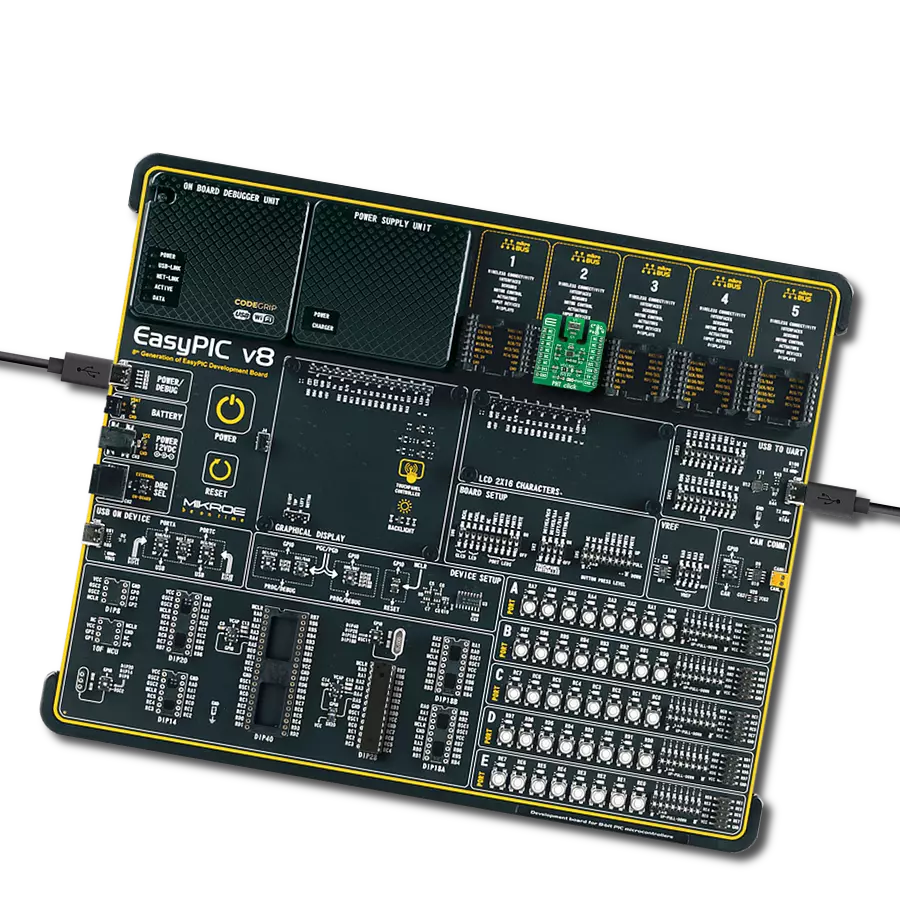
Dev. board
Clicker 2 for Kinetis
Compiler
NECTO Studio
MCU
MK64FN1M0VDC12
Craft environments that strike the perfect balance between comfort and health by using precise humidity and air quality data to inform your adjustments
A
A
Hardware Overview
How does it work?
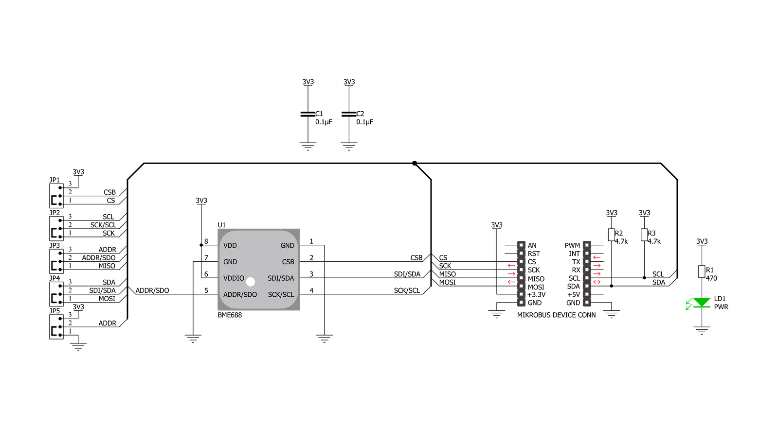
Environment 3 Click is based on the BME688, air quality MEMS sensor that combines gas, humidity, temperature, and barometric pressure sensing from Bosch Sensortec. The BME688 combines reliable high-precision sensors with wide-ranging gas detection and innovative AI capabilities, enabling users to rapidly develop various applications to improve well-being, lifestyle, and sustainability. It offers reduced power consumption, improved accuracy specifications, and a configurable host interface for the fastest data transfer. It covers extended operating pressure, humidity, and temperature ranges from 300-1100hPa, 0-100%RH and from -40°C to +85°C with the accuracy of ±3%RH and ±0.5°C. The BME688 supports a full suite of operational modes, which provides vast flexibility in optimizing
the device for power consumption, resolution, and filter performance. Additionally, it also has a gas scanner function; it can detect Volatile Organic Compounds (VOCs), Volatile Sulfur Compounds (VSCs), and other gases such as carbon monoxide and hydrogen in the part per billion (ppb) range. In standard configuration, the presence of VSCs is being detected as an indicator for, e.g., bacteria growth, where the gas scanner can be customized for sensitivity, selectivity, data rate, and power consumption. Based on its main features listed above, this Click board is the best choice for indoor and outdoor air quality measurement applications, detection of unusual gases that might indicate leakage or fire, early detection of odors and bad smells, and other various temperature and humidity-related applications. Environment 3 Click
allows using both I2C and SPI interfaces. The selection can be made by positioning SMD jumpers labeled COMM SEL in an appropriate position. Note that all the jumpers' positions must be on the same side, or the Click board™ may become unresponsive. While the I2C interface is selected, the BME688 allows choosing the least significant bit (LSB) of its I2C slave address using the SMD jumper labeled ADDR SEL to an appropriate position marked as 0 or 1. This Click board™ can be operated only with a 3.3V logic voltage level. The board must perform appropriate logic voltage level conversion before using MCUs with different logic levels. Also, it comes equipped with a library containing functions and an example code that can be used, as a reference, for further development.


Features overview
Development board
Clicker 2 for Kinetis is a compact starter development board that brings the flexibility of add-on Click boards™ to your favorite microcontroller, making it a perfect starter kit for implementing your ideas. It comes with an onboard 32-bit ARM Cortex-M4F microcontroller, the MK64FN1M0VDC12 from NXP Semiconductors, two mikroBUS™ sockets for Click board™ connectivity, a USB connector, LED indicators, buttons, a JTAG programmer connector, and two 26-pin headers for interfacing with external electronics. Its compact design with clear and easily recognizable silkscreen markings allows you to build gadgets with unique functionalities and
features quickly. Each part of the Clicker 2 for Kinetis development kit contains the components necessary for the most efficient operation of the same board. In addition to the possibility of choosing the Clicker 2 for Kinetis programming method, using a USB HID mikroBootloader or an external mikroProg connector for Kinetis programmer, the Clicker 2 board also includes a clean and regulated power supply module for the development kit. It provides two ways of board-powering; through the USB Micro-B cable, where onboard voltage regulators provide the appropriate voltage levels to each component on the board, or
using a Li-Polymer battery via an onboard battery connector. All communication methods that mikroBUS™ itself supports are on this board, including the well-established mikroBUS™ socket, reset button, and several user-configurable buttons and LED indicators. Clicker 2 for Kinetis is an integral part of the Mikroe ecosystem, allowing you to create a new application in minutes. Natively supported by Mikroe software tools, it covers many aspects of prototyping thanks to a considerable number of different Click boards™ (over a thousand boards), the number of which is growing every day.

Microcontroller Overview
MCU Card / MCU

Architecture
ARM Cortex-M4
MCU Memory (KB)
1024
Silicon Vendor
NXP
Pin count
121
RAM (Bytes)
262144
Used MCU Pins
mikroBUS™ mapper
Take a closer look
Click board™ Schematic
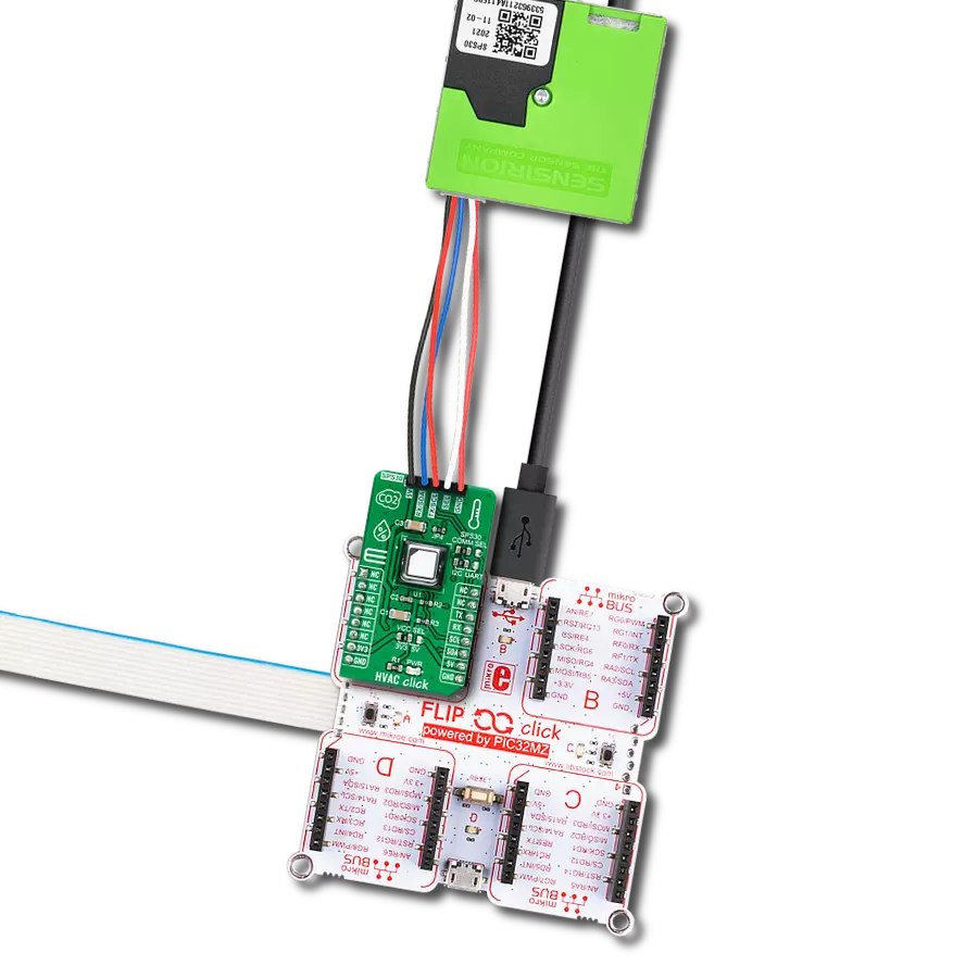
Step by step
Project assembly

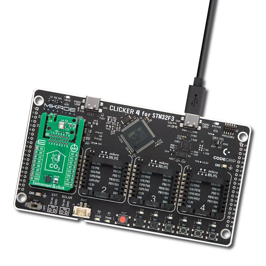
Start by selecting your development board and Click board™. Begin with the Clicker 2 for Kinetis as your development board.


Software Support
Library Description
This library contains API for Environment 3 Click driver.
Key functions:
environment3_get_all_data- This function reads the temperature, humidity, pressure, and gas resistance data from the sensorenvironment3_enable_heater- This function enables or disables the gas sensor heaterenvironment3_soft_reset- This function soft-resets the sensor
Open Source
Code example
The complete application code and a ready-to-use project are available through the NECTO Studio Package Manager for direct installation in the NECTO Studio. The application code can also be found on the MIKROE GitHub account.
/*!
 * @file main.c
 * @brief Environment3 Click example
 *
 * # Description
 * This example demonstrates the use of Environment 3 Click board.
 *
 * The demo application is composed of two sections :
 *
 * ## Application Init
 * Initializes the driver, sets the default configuration, and disables the gas sensor heater.
 *
 * ## Application Task
 * Reads the temperature, humidity, pressure, and gas resistance data from the sensor and
 * displays all values on the USB UART approximately every second.
 *
 * @note
 * The heater is disabled by default, enable it in the Application Init if you need gas resistance data.
 * Gas resistance data is RAW data, if you need VOCs, please contact Bosch Sensortec for VOC calculation library.
 * The temperature and humidity data don't represent the real environmental data when the heater is enabled.
 *
 * @author Stefan Filipovic
 *
 */

#include "board.h"
#include "log.h"
#include "environment3.h"

static environment3_t environment3;
static log_t logger;

void application_init ( void )
{
    log_cfg_t log_cfg;                    /**< Logger config object. */
    environment3_cfg_t environment3_cfg;  /**< Click config object. */

    /**
     * Logger initialization.
     * Default baud rate: 115200
     * Default log level: LOG_LEVEL_DEBUG
     * @note If USB_UART_RX and USB_UART_TX
     * are defined as HAL_PIN_NC, you will
     * need to define them manually for log to work.
     * See @b LOG_MAP_USB_UART macro definition for detailed explanation.
     */
    LOG_MAP_USB_UART( log_cfg );
    log_init( &logger, &log_cfg );
    log_info( &logger, " Application Init " );

    // Click initialization.

    environment3_cfg_setup( &environment3_cfg );
    ENVIRONMENT3_MAP_MIKROBUS( environment3_cfg, MIKROBUS_1 );
    err_t init_flag  = environment3_init( &environment3, &environment3_cfg );
    if ( ( I2C_MASTER_ERROR == init_flag ) || ( SPI_MASTER_ERROR == init_flag ) )
    {
        log_error( &logger, " Application Init Error. " );
        log_info( &logger, " Please, run program again... " );

        for ( ; ; );
    }

    if ( ENVIRONMENT3_OK != environment3_default_cfg ( &environment3 ) )
    {
        log_error( &logger, " Default Config Error. " );
        log_info( &logger, " Please, run program again... " );

        for ( ; ; );
    }

    environment3_enable_heater ( &environment3, ENVIRONMENT3_DISABLE );
    log_info( &logger, " Application Task " );
}

void application_task ( void )
{
    float temperature, pressure, humidity;
    uint32_t gas_resistance;
    if ( ENVIRONMENT3_OK == environment3_get_all_data ( &environment3,
                                                        &temperature,
                                                        &humidity,
                                                        &pressure,
                                                        &gas_resistance ) )
    {
        log_printf( &logger, " Temperature : %.2f C\r\n", temperature );

        log_printf( &logger, " Humidity : %.2f %%\r\n", humidity );

        log_printf( &logger, " Pressure : %.3f mBar\r\n", pressure );

        if ( ENVIRONMENT3_ENABLE == environment3.gas_sett.enable )
        {
            log_printf( &logger, " Gas Resistance : %ld Ohms\r\n", gas_resistance );
            log_printf( &logger, "--------------------------------\r\n" );
        }
        else
        {
            log_printf( &logger, "--------------------------------\r\n" );
            Delay_ms ( 1000 );
        }
    }
}

int main ( void )
{
    /* Do not remove this line or clock might not be set correctly. */
    #ifdef PREINIT_SUPPORTED
    preinit();
    #endif

    application_init( );

    for ( ; ; )
    {
        application_task( );
    }

    return 0;
}

// ------------------------------------------------------------------------ END
Additional Support
Resources
Category:Environmental