Understand both the movement and the magnetic environment with NMH1000, FXLS8974CF and MK64FN1M0VDC12
Smart tool that can tell you if something is moving and whether there are any magnetic changes around it

Published Jan 24, 2024
Click board™
Mag&Accel Click
Dev. board
Clicker 2 for Kinetis
Compiler
NECTO Studio
MCU
MK64FN1M0VDC12
From smart security to intelligent automation, redefine how you interact with the world!
A
A
Hardware Overview
How does it work?
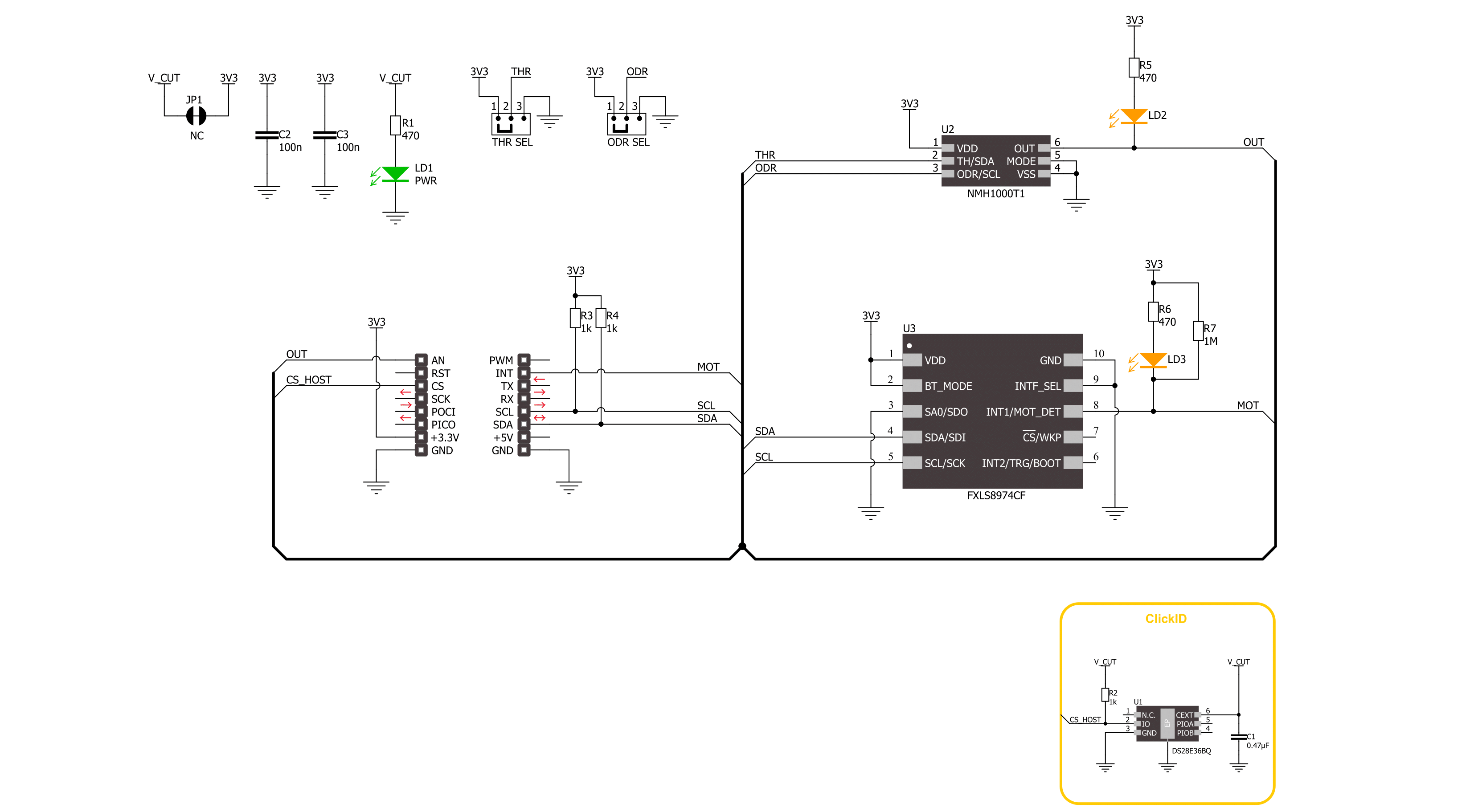
Mag&Accel Click is based on the NMH1000, a Hall-effect magnetic field switch, and the FXLS8974CF, a 3-axis low-g accelerometer, both from NXP Semiconductor. The switch processes its input over the functional blocks that consist of a configurable state machine, an analog-to-voltage conversion of the input, and a comparison to generate the bi-state output. The output is arranged in a linear succession. The NMH1000 has a transducer that generates a small charge proportional to the proximal magnetic flux density. The Hall-effect charge is converted to voltage and compared with the pre-defined threshold voltage. This determines the state of the switch's output. The FXLS8974CF accelerometer has a ±2/4/8/16 g user-selectable, full-scale measurement range with a 12-bit
acceleration data output. It can work in several modes, such as active, hibernate, standby, and more. The integrated FIFO/LIFO buffer of 144 bytes can store 32 12-bit X/Y/Z/ data triplets. The sensor also has flexible data change detection, such as motion, freefall, and other inertial events. Mag&Accel Click uses a standard 2-wire I2C interface to allow the host MCU to communicate with the accelerometer. The FXLS8974CF uses a motion MOT pin to interrupt the host MCU if the motion is detected, with an accompanying Motion LED for a visual presentation. The NMH1000 is set in a standalone mode. The output of the magnetic switch, according to the pre-defined threshold, is available over the output OUT pin and, in addition, over the Field LED for visual presentation. The
threshold itself can be set over the THR SEL jumper between high, medium, and low thresholds (±230, ±160, ±100G). You can also set the sampling rate over the ODR SEL jumper between high, medium, and low (10, 1, 0.1Hz). In addition, there is an LP Cut jumper at the bottom of the Mag&Accel Click board™, with which a low power consumption feature can be achieved. This Click board™ can be operated only with a 3.3V logic voltage level. The board must perform appropriate logic voltage level conversion before using MCUs with different logic levels. Also, it comes equipped with a library containing functions and an example code that can be used as a reference for further development.

Features overview
Development board
Clicker 2 for Kinetis is a compact starter development board that brings the flexibility of add-on Click boards™ to your favorite microcontroller, making it a perfect starter kit for implementing your ideas. It comes with an onboard 32-bit ARM Cortex-M4F microcontroller, the MK64FN1M0VDC12 from NXP Semiconductors, two mikroBUS™ sockets for Click board™ connectivity, a USB connector, LED indicators, buttons, a JTAG programmer connector, and two 26-pin headers for interfacing with external electronics. Its compact design with clear and easily recognizable silkscreen markings allows you to build gadgets with unique functionalities and
features quickly. Each part of the Clicker 2 for Kinetis development kit contains the components necessary for the most efficient operation of the same board. In addition to the possibility of choosing the Clicker 2 for Kinetis programming method, using a USB HID mikroBootloader or an external mikroProg connector for Kinetis programmer, the Clicker 2 board also includes a clean and regulated power supply module for the development kit. It provides two ways of board-powering; through the USB Micro-B cable, where onboard voltage regulators provide the appropriate voltage levels to each component on the board, or
using a Li-Polymer battery via an onboard battery connector. All communication methods that mikroBUS™ itself supports are on this board, including the well-established mikroBUS™ socket, reset button, and several user-configurable buttons and LED indicators. Clicker 2 for Kinetis is an integral part of the Mikroe ecosystem, allowing you to create a new application in minutes. Natively supported by Mikroe software tools, it covers many aspects of prototyping thanks to a considerable number of different Click boards™ (over a thousand boards), the number of which is growing every day.

Microcontroller Overview
MCU Card / MCU

Architecture
ARM Cortex-M4
MCU Memory (KB)
1024
Silicon Vendor
NXP
Pin count
121
RAM (Bytes)
262144
Used MCU Pins
mikroBUS™ mapper
Take a closer look
Click board™ Schematic
Step by step
Project assembly

Start by selecting your development board and Click board™. Begin with the Clicker 2 for Kinetis as your development board.


Track your results in real time
Application Output
1. Application Output - In Debug mode, the 'Application Output' window enables real-time data monitoring, offering direct insight into execution results. Ensure proper data display by configuring the environment correctly using the provided tutorial.

2. UART Terminal - Use the UART Terminal to monitor data transmission via a USB to UART converter, allowing direct communication between the Click board™ and your development system. Configure the baud rate and other serial settings according to your project's requirements to ensure proper functionality. For step-by-step setup instructions, refer to the provided tutorial.

3. Plot Output - The Plot feature offers a powerful way to visualize real-time sensor data, enabling trend analysis, debugging, and comparison of multiple data points. To set it up correctly, follow the provided tutorial, which includes a step-by-step example of using the Plot feature to display Click board™ readings. To use the Plot feature in your code, use the function: plot(*insert_graph_name*, variable_name);. This is a general format, and it is up to the user to replace 'insert_graph_name' with the actual graph name and 'variable_name' with the parameter to be displayed.

Software Support
Library Description
This library contains API for Mag&Accel Click driver.
Key functions:
magaccel_get_axes_data- This function reads the accelerometer sensor axes data.magaccel_set_op_mode- This function sets the desired operating mode of the sensor.magaccel_check_mag_field- This function checks the magnetic field y by reading the states of the FLD (AN) pin.
Open Source
Code example
The complete application code and a ready-to-use project are available through the NECTO Studio Package Manager for direct installation in the NECTO Studio. The application code can also be found on the MIKROE GitHub account.
/*!
 * @file main.c
 * @brief MagAccel Click example
 *
 * # Description
 * This library contains API for the MagAccel Click driver.
 * The library initializes and defines the I2C drivers to
 * write and read data from registers, as well as the default
 * configuration for reading accelerator data.
 *
 * The demo application is composed of two sections :
 *
 * ## Application Init
 * The initialization of the I2C module, log UART, and additional pins.
 * After the driver init, the app executes a default configuration.
 *
 * ## Application Task
 * This example demonstrates the use of the MagAccel Click board.
 * Measures and displays acceleration data for the X-axis, Y-axis, and Z-axis
 * and the presence of a magnetic field.
 * Results are being sent to the UART Terminal, where you can track their changes.
 *
 * @author Nenad Filipovic
 *
 */

#include "board.h"
#include "log.h"
#include "magaccel.h"

static magaccel_t magaccel;
static log_t logger;

void application_init ( void )
{
    log_cfg_t log_cfg;  /**< Logger config object. */
    magaccel_cfg_t magaccel_cfg;  /**< Click config object. */

    /**
     * Logger initialization.
     * Default baud rate: 115200
     * Default log level: LOG_LEVEL_DEBUG
     * @note If USB_UART_RX and USB_UART_TX
     * are defined as HAL_PIN_NC, you will
     * need to define them manually for log to work.
     * See @b LOG_MAP_USB_UART macro definition for detailed explanation.
     */
    LOG_MAP_USB_UART( log_cfg );
    log_init( &logger, &log_cfg );
    log_info( &logger, " Application Init " );

    // Click initialization.
    magaccel_cfg_setup( &magaccel_cfg );
    MAGACCEL_MAP_MIKROBUS( magaccel_cfg, MIKROBUS_1 );
    if ( I2C_MASTER_ERROR == magaccel_init( &magaccel, &magaccel_cfg ) )
    {
        log_error( &logger, " Communication init." );
        for ( ; ; );
    }

    if ( MAGACCEL_ERROR == magaccel_default_cfg ( &magaccel ) )
    {
        log_error( &logger, " Default configuration." );
        for ( ; ; );
    }

    log_info( &logger, " Application Task " );
    log_printf( &logger, "_________________\r\n" );
}

void application_task ( void )
{
    if ( MAGACCEL_DATA_READY == magaccel_check_data_ready( &magaccel ) )
    {
        magaccel_axes_t acc_axis;
        magaccel_get_axes_data( &magaccel, &acc_axis );

        if ( MAGACCEL_DET_MAG_FIELD == magaccel_check_mag_field( &magaccel ) )
        {
            log_printf( &logger, " Presence of a magnetic field\r\n" );
            log_printf( &logger, "_________________\r\n" );
        }

        log_printf( &logger, " Accel X: %.2f mg\r\n", acc_axis.x );
        log_printf( &logger, " Accel Y: %.2f mg\r\n", acc_axis.y );
        log_printf( &logger, " Accel Z: %.2f mg\r\n", acc_axis.z );
        log_printf( &logger, "_________________\r\n" );
        Delay_ms ( 100 );
    }
}

int main ( void )
{
    /* Do not remove this line or clock might not be set correctly. */
    #ifdef PREINIT_SUPPORTED
    preinit();
    #endif

    application_init( );

    for ( ; ; )
    {
        application_task( );
    }

    return 0;
}

// ------------------------------------------------------------------------ END


