Enjoy in various high-power lighting applications with TPS61160A and MK64FN1M0VDC12
Shine brighter, last longer

Published Sep 05, 2023
Click board™
LED Driver 4 Click
Dev. board
Clicker 2 for Kinetis
Compiler
NECTO Studio
MCU
MK64FN1M0VDC12
Experience enhanced efficiency and performance in your electronic designs by incorporating our reliable LED driver solution
A
A
Hardware Overview
How does it work?
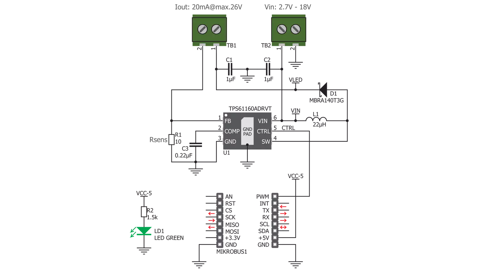
LED Driver 4 Click is based on the TPS61160A, a white LED driver with PWM brightness control, from Texas Instruments. The TPS61160A driver uses the boost converter topology with the current mode control. Its operation is very similar to a typical boost DC-DC converter with some additional features, useful for LED array driving. The Click board™ can provide up to 26V on the output terminals, after which the open LED sensing section will shut down the output stage MOSFET and the IC itself as a protection measure. This prevents the output voltage from exceeding the maximum ratings of the device in the case when the output LED is disconnected. The same will happen if the voltage at the feedback pin drops under 50% of its nominal value, 200 mV. The TPS61160A allows the PWM signal to be applied to its CTRL input, routed to the PWM pin of the mikroBUS™, labeled as CTL. The signal applied to this pin will modulate the feedback voltage on the FB pin, which, after being filtered through the LP filter, reduces the DC current on the output and through the LED array. This dimming technique will not produce any noise, as the DC current is scaled down, while the PWM is applied only to the internal feedback voltage. The PWM frequency should stay within 5 kHz to 100 kHz for optimum performance. The current through the LED
segments is sensed via the onboard resistor connected between the GND and the FB pin. It is chosen so that the maximum LED current is 20 mA. This is the optimal current for the white LEDs, providing the maximum brightness without LED deterioration. Note that while this is true for most of the white LEDs, the datasheet of the particular LEDs used with the LED Driver 4 click should be checked for the forward current parameter. It should be at least 20 mA. As explained above, the dimming function will reduce this current, resulting in a dimmer LED light. A soft-start function is built into the device, and it slowly ramps the voltage at the FB pin, resulting in a slow increase of the output voltage over about 6 ms, preventing high inrush currents. The internal current limit is also set to half the maximum current specification for the first 5 ms of operation. Applying the LOW logic level to the CTL pin for more than 2.5 ms will put the device into Shutdown mode. While in Shutdown mode, the current consumption is minimal. However, a current path still exists through the inductor and the Schottky diode. To prevent unwanted activation of the LED array, the minimum forward voltage of the LED array should be above the input voltage. The power supply for the LED array is connected via the VIN screw terminal, allowing an
external power source to be used. The rating of the external power source should stay within the range of 2V to 18V. The second screw terminal with the LED icon underneath connects the LED array. The maximum forward voltage of the LED array should stay below the device's minimum overprotection voltage, typically 25V. The maximum forward voltage of the LED element depends on the used LED type. It can be found in the datasheet of the used LED. The minimum overprotection voltage of the TPS61160A IC can be found in the TPS61160A, but it is also available in the Electrical Characteristics table below. Click board™ itself is powered via 5V mikroBUS™ rail. However, the Click board™ allows both 3.3V and 5V MCUs to drive its CTL input, as long as the voltage for the LOW logic level stays under 0.4V and the voltage for the HIGH logic level applied to this pin stays above 1.2V. The use of the Led Driver 4 click is easy and straightforward. However, MikroElektronika provides a library that contains functions compatible with the MikroElektronika compilers, which can be used for simplified LED array driving. The library also contains an example application that demonstrates their use. This example application can be used as a reference for custom designs.

Features overview
Development board
Clicker 2 for Kinetis is a compact starter development board that brings the flexibility of add-on Click boards™ to your favorite microcontroller, making it a perfect starter kit for implementing your ideas. It comes with an onboard 32-bit ARM Cortex-M4F microcontroller, the MK64FN1M0VDC12 from NXP Semiconductors, two mikroBUS™ sockets for Click board™ connectivity, a USB connector, LED indicators, buttons, a JTAG programmer connector, and two 26-pin headers for interfacing with external electronics. Its compact design with clear and easily recognizable silkscreen markings allows you to build gadgets with unique functionalities and
features quickly. Each part of the Clicker 2 for Kinetis development kit contains the components necessary for the most efficient operation of the same board. In addition to the possibility of choosing the Clicker 2 for Kinetis programming method, using a USB HID mikroBootloader or an external mikroProg connector for Kinetis programmer, the Clicker 2 board also includes a clean and regulated power supply module for the development kit. It provides two ways of board-powering; through the USB Micro-B cable, where onboard voltage regulators provide the appropriate voltage levels to each component on the board, or
using a Li-Polymer battery via an onboard battery connector. All communication methods that mikroBUS™ itself supports are on this board, including the well-established mikroBUS™ socket, reset button, and several user-configurable buttons and LED indicators. Clicker 2 for Kinetis is an integral part of the Mikroe ecosystem, allowing you to create a new application in minutes. Natively supported by Mikroe software tools, it covers many aspects of prototyping thanks to a considerable number of different Click boards™ (over a thousand boards), the number of which is growing every day.

Microcontroller Overview
MCU Card / MCU

Architecture
ARM Cortex-M4
MCU Memory (KB)
1024
Silicon Vendor
NXP
Pin count
121
RAM (Bytes)
262144
Used MCU Pins
mikroBUS™ mapper
Take a closer look
Click board™ Schematic
Step by step
Project assembly

Start by selecting your development board and Click board™. Begin with the Clicker 2 for Kinetis as your development board.


Software Support
Library Description
This library contains API for LED Driver 4 Click driver.
Key functions:
leddriver4_set_duty_cycle- Generic sets PWM duty cycleleddriver4_pwm_stop- Stop PWM moduleleddriver4_pwm_start- Start PWM module.
Open Source
Code example
The complete application code and a ready-to-use project are available through the NECTO Studio Package Manager for direct installation in the NECTO Studio. The application code can also be found on the MIKROE GitHub account.
/*!
 * @file
 * @brief LedDriver4 Click example
 *
 * # Description
 * This Click has the ability to dim the connected LED array, without producing any noise on the output.
 *
 * The demo application is composed of two sections :
 *
 * ## Application Init
 * Initializes the GPIO driver and
 * configures the PWM peripheral for controlling the LED array intensity.
 *
 * ## Application Task
 * Increases and decreases LED array intensity
 * ( first increases light intensity to the maximum and then decreases to the minimum ).
 * Results are being sent to the Usart Terminal where you can track their changes.
 *
 *
 * @author Nikola Peric
 *
 */
// ------------------------------------------------------------------- INCLUDES

#include "board.h"
#include "log.h"
#include "leddriver4.h"

// ------------------------------------------------------------------ VARIABLES

static leddriver4_t leddriver4;
static log_t logger;

// ------------------------------------------------------ APPLICATION FUNCTIONS

void application_init ( void )
{
    log_cfg_t log_cfg;
    leddriver4_cfg_t cfg;

    /**
     * Logger initialization.
     * Default baud rate: 115200
     * Default log level: LOG_LEVEL_DEBUG
     * @note If USB_UART_RX and USB_UART_TX
     * are defined as HAL_PIN_NC, you will
     * need to define them manually for log to work.
     * See @b LOG_MAP_USB_UART macro definition for detailed explanation.
     */
    LOG_MAP_USB_UART( log_cfg );
    log_init( &logger, &log_cfg );
    log_info( &logger, "---- Application Init ----" );

    //  Click initialization.

    leddriver4_cfg_setup( &cfg );
    LEDDRIVER4_MAP_MIKROBUS( cfg, MIKROBUS_1 );
    leddriver4_init( &leddriver4, &cfg );

    leddriver4_set_duty_cycle ( &leddriver4, 0.0 );
    leddriver4_pwm_start( &leddriver4 );
    log_info( &logger, "---- Application Task ----" );
    Delay_ms ( 500 );
}

void application_task ( void )
{
    static int8_t duty_cnt = 1;
    static int8_t duty_inc = 1;
    float duty = duty_cnt / 10.0;

    leddriver4_set_duty_cycle ( &leddriver4, duty );
    log_printf( &logger, "Duty: %d%%\r\n", ( uint16_t )( duty_cnt * 10 ) );
    Delay_ms ( 500 );

    if ( 10 == duty_cnt )
    {
        duty_inc = -1;
    }
    else if ( 0 == duty_cnt )
    {
        duty_inc = 1;
    }
    duty_cnt += duty_inc;
}

int main ( void )
{
    /* Do not remove this line or clock might not be set correctly. */
    #ifdef PREINIT_SUPPORTED
    preinit();
    #endif

    application_init( );

    for ( ; ; )
    {
        application_task( );
    }

    return 0;
}


// ------------------------------------------------------------------------ END
Additional Support
Resources
Category:LED Drivers


