Redefine timekeeping for the modern age with PCF2123 and STM32F756ZG
Time matters: Unleash the power of precision with our RTC solution

Published Oct 21, 2023
Click board™
RTC 13 Click
Dev. board
UNI Clicker
Compiler
NECTO Studio
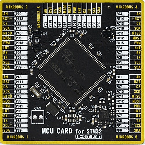
MCU
STM32F756ZG
Elevate your engineering solutions with our advanced real-time clock, ensuring accurate time tracking and synchronization
A
A
Hardware Overview
How does it work?
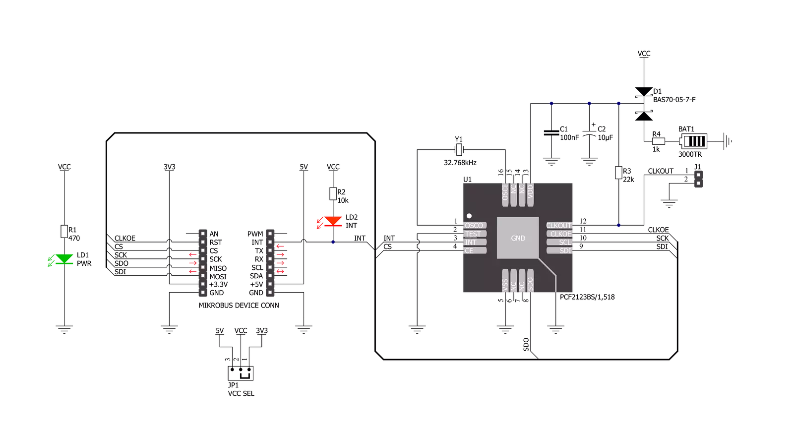
RTC 13 Click is based on the PCF2123, an SPI configurable real-time clock/calendar optimized for low-power operations from NXP Semiconductors. It contains sixteen 8-bit registers with an auto-incrementing address counter, an on-chip 32.768kHz oscillator with two integrated load capacitors, a frequency divider that provides the source clock for the RTC, and a programmable clock output. The integrated oscillator ensures year, month, day, weekday, hours, minutes, and seconds, making this Click board™ suitable for various time-keeping applications such as high-duration timers, daily alarms, and more. The PCF2123 communicates with MCU using the standard SPI serial interface with a maximum
frequency of 8MHz, where data transfers serially with a maximum data rate of 6.25 Mbit/s. An alarm and timer function is also available, providing the possibility to generate a wake-up signal on an interrupt line, available on the INT pin of the mikroBUS™ socket and indicated by a red LED marked as INT. Besides, this Click board™ also has an onboard header labeled CLKOUT, which provides a programmable square-wave output clock signal controlled by one GPIO pin, a CLE pin routed to the RTS pin, the mikroBUS™ socket. Frequencies of 32.768kHz, representing a default value of 1Hz, can be generated and used as a system and MCU clock, input to a charge pump, or oscillator calibration. Like this one, the most
common RTC configuration is a battery-backed-up, which maintains time and continues its work without interruption during a power failure. That’s why, besides the PCF2123, the RTC 13 Click has a button cell battery holder compatible with the 3000TR battery holder, suitable for 12mm Coin Cell batteries. This Click board™ can operate with either 3.3V or 5V logic voltage levels selected via the VCC SEL jumper. This way, both 3.3V and 5V capable MCUs can use the communication lines properly. Also, this Click board™ comes equipped with a library containing easy-to-use functions and an example code that can be used as a reference for further development.


Features overview
Development board
UNI Clicker is a compact development board designed as a complete solution that brings the flexibility of add-on Click boards™ to your favorite microcontroller, making it a perfect starter kit for implementing your ideas. It supports a wide range of microcontrollers, such as different ARM, PIC32, dsPIC, PIC, and AVR from various vendors like Microchip, ST, NXP, and TI (regardless of their number of pins), four mikroBUS™ sockets for Click board™ connectivity, a USB connector, LED indicators, buttons, a debugger/programmer connector, and two 26-pin headers for interfacing with external electronics. Thanks to innovative manufacturing technology, it allows you to build
gadgets with unique functionalities and features quickly. Each part of the UNI Clicker development kit contains the components necessary for the most efficient operation of the same board. In addition to the possibility of choosing the UNI Clicker programming method, using a third-party programmer or CODEGRIP/mikroProg connected to onboard JTAG/SWD header, the UNI Clicker board also includes a clean and regulated power supply module for the development kit. It provides two ways of board-powering; through the USB Type-C (USB-C) connector, where onboard voltage regulators provide the appropriate voltage levels to each component on the board, or using a Li-Po/Li
Ion battery via an onboard battery connector. All communication methods that mikroBUS™ itself supports are on this board (plus USB HOST/DEVICE), including the well-established mikroBUS™ socket, a standardized socket for the MCU card (SiBRAIN standard), and several user-configurable buttons and LED indicators. UNI Clicker is an integral part of the Mikroe ecosystem, allowing you to create a new application in minutes. Natively supported by Mikroe software tools, it covers many aspects of prototyping thanks to a considerable number of different Click boards™ (over a thousand boards), the number of which is growing every day.

Microcontroller Overview
MCU Card / MCU
Type
8th Generation
Architecture
ARM Cortex-M7
MCU Memory (KB)
1024
Silicon Vendor
STMicroelectronics
Pin count
144
RAM (Bytes)
327680
Used MCU Pins
mikroBUS™ mapper
Take a closer look
Click board™ Schematic
Step by step
Project assembly

Start by selecting your development board and Click board™. Begin with the UNI Clicker as your development board.


Software Support
Library Description
This library contains API for RTC 13 Click driver.
Key functions:
rtc13_get_time- RTC 13 get time functionrtc13_set_time- RTC 13 set time functionrtc13_get_date- RTC 13 get date function
Open Source
Code example
The complete application code and a ready-to-use project are available through the NECTO Studio Package Manager for direct installation in the NECTO Studio. The application code can also be found on the MIKROE GitHub account.
/*!
 * @file main.c
 * @brief RTC13 Click example
 *
 * # Description
 * This is an example that demonstrates the use of the RTC 13 Click board™.
 *
 * The demo application is composed of two sections :
 *
 * ## Application Init
 * Initialization of SPI module, log UART and additional pins.
 * After driver initialization and default settings,
 * the app set the time to 23:59:50 and set the date to 04.08.2021.
 *
 * ## Application Task
 * This is an example that shows the use of a RTC 13 Click board™.
 * In this example, we read and display the current time and date,
 * which we also previously set.
 * Results are being sent to the Usart Terminal where you can track their changes.
 * All data logs write on USB changes every 1 sec.
 *
 * @author Nenad Filipovic
 *
 */

#include "board.h"
#include "log.h"
#include "rtc13.h"

static rtc13_t rtc13;
static log_t logger;

static uint8_t new_sec = 255;
static rtc13_time_t time;
static rtc13_date_t date;

void application_init ( void )
{
    log_cfg_t log_cfg;      /**< Logger config object. */
    rtc13_cfg_t rtc13_cfg;  /**< Click config object. */

    /**
     * Logger initialization.
     * Default baud rate: 115200
     * Default log level: LOG_LEVEL_DEBUG
     * @note If USB_UART_RX and USB_UART_TX
     * are defined as HAL_PIN_NC, you will
     * need to define them manually for log to work.
     * See @b LOG_MAP_USB_UART macro definition for detailed explanation.
     */
    LOG_MAP_USB_UART( log_cfg );
    log_init( &logger, &log_cfg );
    log_info( &logger, " Application Init " );

    // Click initialization.

    rtc13_cfg_setup( &rtc13_cfg );
    RTC13_MAP_MIKROBUS( rtc13_cfg, MIKROBUS_1 );
    err_t init_flag  = rtc13_init( &rtc13, &rtc13_cfg );
    if ( SPI_MASTER_ERROR == init_flag )
    {
        log_error( &logger, " Application Init Error. " );
        log_info( &logger, " Please, run program again... " );

        for ( ; ; );
    }

    rtc13_default_cfg ( &rtc13 );
    log_info( &logger, " Application Task " );
    Delay_ms ( 100 );

    date.weekday = 3;
    date.day = 4;
    date.month = 8;
    date.year = 21;
    rtc13_set_date( &rtc13, date );
    Delay_ms ( 100 );

    time.hours = 23;
    time.min = 59;
    time.sec = 50;
    rtc13_set_time( &rtc13, time );
    Delay_ms ( 100 );
}

void application_task ( void )
{
    rtc13_get_time( &rtc13, &time );
    Delay_ms ( 1 );
    rtc13_get_date( &rtc13, &date );
    Delay_ms ( 1 );

    if ( time.sec != new_sec )
    {
        log_printf( &logger, "  Date      : %.2d-%.2d-%.2d\r\n", ( uint16_t ) date.day, ( uint16_t ) date.month, ( uint16_t ) date.year );
        log_printf( &logger, "  Time      : %.2d:%.2d:%.2d\r\n", ( uint16_t ) time.hours, ( uint16_t ) time.min, ( uint16_t ) time.sec );
        log_printf( &logger, "- - - - - - - - - - - -\r\n" );
        new_sec = time.sec;
        Delay_ms ( 1 );
     }
}

int main ( void )
{
    /* Do not remove this line or clock might not be set correctly. */
    #ifdef PREINIT_SUPPORTED
    preinit();
    #endif

    application_init( );

    for ( ; ; )
    {
        application_task( );
    }

    return 0;
}

// ------------------------------------------------------------------------ END


