Conquer the challenges of autonomy with multi-band RTK GNSS solution based on ZED-F9R-02B and MK20DX128VFM5
Precision in every dimension
Published Sep 02, 2023
Click board™
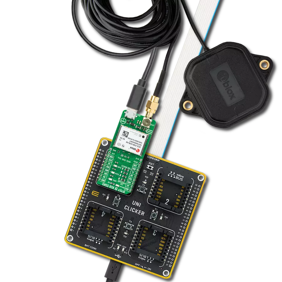
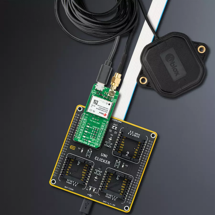
GNSS RTK 2 Click
Dev. board
UNI Clicker
Compiler
NECTO Studio
MCU
MK20DX128VFM5
Our multi-band RTK GNSS solution stands as the beacon of precision in the face of complex multipath environments. Designed to excel where others falter, it's the ideal navigation companion for modern autonomous robotics applications.
A
A
Hardware Overview
How does it work?
GNSS RTK 2 Click is based on the ZED-F9R, a multi-band professional-grade GNSS positioning module featuring the u-blox F9 receiver platform, providing a reliable multi-band GNSS sensor fusion solution for industrial applications. Thanks to the multi-band RF front-end architecture, all four major GNSS constellations (GPS, GLONASS, Galileo, and BeiDou) plus SBAS and QZSS satellites can be received concurrently. The ZED-F9R high-performance sensor fusion module also has an integrated inertial measurement unit (IMU) for centimeter-level accuracy RTK positioning (RTK rover feature). The ZED-F9R's built-in algorithms fuse the IMU data, GNSS measurements, wheel ticks, correction data, and a vehicle dynamics model to provide optimal positioning accuracy where GNSS alone would fail. The module operates in the open sky, in the wooded countryside, in demanding multipath environments, and even in challenging environments such as cities. Designed for industrial applications, ZED-F9R is the ultimate solution for a data-driven economy where control and position availability are crucial. This module represents a turnkey self-contained solution, eliminating the technical risk and effort of selecting and integrating RF components and third-party libraries such as precise positioning engines. It also supports a range of correction services, RTCM or SPARTN-formatted corrections, enabling high-precision navigation using internet or satellite data through an unpopulated UART
header in the middle of the board. This interface allows each application to optimize performance according to the application's unique needs. GNSS RTK 2 Click communicates with an MCU using the UART interface at 115200bps as its default communication protocol. Users can use other interfaces, such as SPI and I2C, to configure the module and write the library themselves. The interface is selected by positioning SMD jumpers labeled COMM SEL in an appropriate position. When choosing the SPI communication, with the correct selection of the COMM SEL jumpers, it is also necessary to populate the DSEL jumper to configure the interface pins as SPI. In the default state, the jumper labeled as DSEL is unpopulated. The receiver also can enter a Safe-Boot mode. When the jumper labeled SFBT is populated, the receiver starts in Safe-Boot mode, and the GNSS operation is disabled. The USB interface, compatible with USB version 2.0 (Full Speed, 12 Mbit/s), can be used for communication as an alternative to the UART. The USB port can be used as an additional power supply if the Click board™ is required to be a standalone device. In case of a mains supply failure, the module can use a backup supply voltage from a connected battery. Backup voltage supplies the real-time clock and battery-backed RAM and enables all relevant data to be saved in the backup RAM to allow a hot or warm start later. In addition to these features, this board also uses several mikroBUS™ socket pins. RDY pin routed to the AN pin of the mikroBUS™ socket is
used as a communication indicator when bytes are ready to be transmitted. The RST pin routed on the PWM pin of the mikroBUS™ socket provides the general reset ability, and the TMP pin, alongside its LED indicator, routed on the INT pin of the mikroBUS™ socket provides one pulse per second time pulse with configurable duration and frequency. The RTK pin routed on the RST pin of the mikroBUS™ socket, alongside an LED indicator labeled RTK, indicates the RTK positioning status. When LED blinks, a valid stream of RTCM messages is received, but no RTK fixed mode has been achieved. When the LED is constantly lit, the LED indicates that RTK mode has been achieved. It also has another LED indicator labeled as GDC that shows the current geofence status of whether the receiver is inside any active areas. For example, this feature can wake a sleeping host when a defined geofence condition is reached. GNSS RTK 2 Click has an SMA antenna connector for connecting an appropriate antenna, also offered by Mikroe, such as a GPS Active External Antenna. This antenna is an excellent choice for all GSM/GPRS applications supporting L1 and L2 band frequencies. This Click board™ can be operated only with a 5V logic voltage level. The board must perform appropriate logic voltage level conversion before using MCUs with different logic levels. However, the Click board™ comes equipped with a library containing functions and an example code that can be used as a reference for further development.

Features overview
Development board
UNI Clicker is a compact development board designed as a complete solution that brings the flexibility of add-on Click boards™ to your favorite microcontroller, making it a perfect starter kit for implementing your ideas. It supports a wide range of microcontrollers, such as different ARM, PIC32, dsPIC, PIC, and AVR from various vendors like Microchip, ST, NXP, and TI (regardless of their number of pins), four mikroBUS™ sockets for Click board™ connectivity, a USB connector, LED indicators, buttons, a debugger/programmer connector, and two 26-pin headers for interfacing with external electronics. Thanks to innovative manufacturing technology, it allows you to build
gadgets with unique functionalities and features quickly. Each part of the UNI Clicker development kit contains the components necessary for the most efficient operation of the same board. In addition to the possibility of choosing the UNI Clicker programming method, using a third-party programmer or CODEGRIP/mikroProg connected to onboard JTAG/SWD header, the UNI Clicker board also includes a clean and regulated power supply module for the development kit. It provides two ways of board-powering; through the USB Type-C (USB-C) connector, where onboard voltage regulators provide the appropriate voltage levels to each component on the board, or using a Li-Po/Li
Ion battery via an onboard battery connector. All communication methods that mikroBUS™ itself supports are on this board (plus USB HOST/DEVICE), including the well-established mikroBUS™ socket, a standardized socket for the MCU card (SiBRAIN standard), and several user-configurable buttons and LED indicators. UNI Clicker is an integral part of the Mikroe ecosystem, allowing you to create a new application in minutes. Natively supported by Mikroe software tools, it covers many aspects of prototyping thanks to a considerable number of different Click boards™ (over a thousand boards), the number of which is growing every day.

Microcontroller Overview
MCU Card / MCU
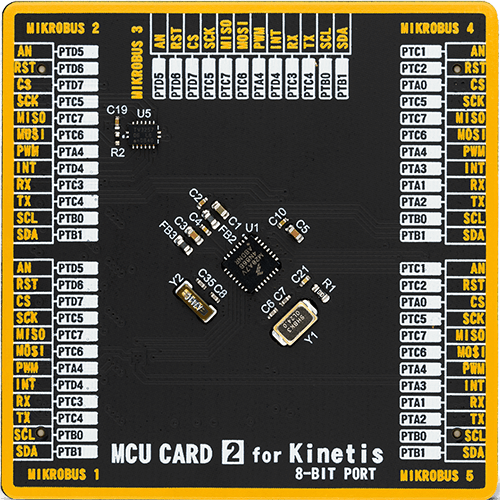
Type
8th Generation
Architecture
ARM Cortex-M4
MCU Memory (KB)
160
Silicon Vendor
NXP
Pin count
32
RAM (Bytes)
16384
You complete me!
Accessories
GNSS Active External Antenna is a unique multi-band type of antenna coming from u-blox that is the perfect selection for high precision GNSS applications, which require highly accurate location abilities such as RTK. The ANN-MB-00 is a multi-band (L1, L2/E5b/B2I) active GNSS antenna with a 5m cable and SMA connector. The antenna supports GPS, GLONASS, Galileo, and BeiDou and includes a high-performance multi-band RHCP dual-feed patch antenna element, a built-in high-gain LNA with SAW pre-filtering, and a 5 m antenna cable with SMA connector, and is waterproof.

Used MCU Pins
mikroBUS™ mapper
Take a closer look
Click board™ Schematic

Step by step
Project assembly

Start by selecting your development board and Click board™. Begin with the UNI Clicker as your development board.


Track your results in real time
Application Output
1. Application Output - In Debug mode, the 'Application Output' window enables real-time data monitoring, offering direct insight into execution results. Ensure proper data display by configuring the environment correctly using the provided tutorial.

2. UART Terminal - Use the UART Terminal to monitor data transmission via a USB to UART converter, allowing direct communication between the Click board™ and your development system. Configure the baud rate and other serial settings according to your project's requirements to ensure proper functionality. For step-by-step setup instructions, refer to the provided tutorial.

3. Plot Output - The Plot feature offers a powerful way to visualize real-time sensor data, enabling trend analysis, debugging, and comparison of multiple data points. To set it up correctly, follow the provided tutorial, which includes a step-by-step example of using the Plot feature to display Click board™ readings. To use the Plot feature in your code, use the function: plot(*insert_graph_name*, variable_name);. This is a general format, and it is up to the user to replace 'insert_graph_name' with the actual graph name and 'variable_name' with the parameter to be displayed.

Software Support
Library Description
This library contains API for GNSS RTK 2 Click driver.
Key functions:
gnssrtk2_reset_device- This function resets the device by toggling the RST pingnssrtk2_generic_read- This function reads a desired number of data bytes from the modulegnssrtk2_parse_gngga- This function parses the GNGGA data from the read response buffer
Open Source
Code example
The complete application code and a ready-to-use project are available through the NECTO Studio Package Manager for direct installation in the NECTO Studio. The application code can also be found on the MIKROE GitHub account.
/*!
 * @file main.c
 * @brief GNSS RTK 2 Click example
 *
 * # Description
 * This example demonstrates the use of GNSS RTK 2 Click by reading and displaying
 * the GNSS coordinates.
 *
 * The demo application is composed of two sections :
 *
 * ## Application Init
 * Initializes the driver and resets the Click board.
 *
 * ## Application Task
 * Reads the received data, parses the GNGGA info from it, and once it receives the position fix
 * it will start displaying the coordinates on the USB UART.
 *
 * ## Additional Function
 * - static void gnssrtk2_clear_app_buf ( void )
 * - static err_t gnssrtk2_process ( gnssrtk2_t *ctx )
 * - static void gnssrtk2_parser_application ( char *rsp )
 *
 * @author Stefan Filipovic
 *
 */

#include "board.h"
#include "log.h"
#include "gnssrtk2.h"

#define PROCESS_BUFFER_SIZE 300

static gnssrtk2_t gnssrtk2;
static log_t logger;

static char app_buf[ PROCESS_BUFFER_SIZE ] = { 0 };
static int32_t app_buf_len = 0;
static int32_t app_buf_cnt = 0;

/**
 * @brief GNSS RTK 2 clearing application buffer.
 * @details This function clears memory of application buffer and reset its length and counter.
 * @return None.
 * @note None.
 */
static void gnssrtk2_clear_app_buf ( void );

/**
 * @brief GNSS RTK 2 data reading function.
 * @details This function reads data from device and concatenates data to application buffer.
 * @param[in] ctx : Click context object.
 * See #gnssrtk2_t object definition for detailed explanation.
 * @return @li @c  0 - Read some data.
 *         @li @c -1 - Nothing is read or Application buffer overflow.
 * See #err_t definition for detailed explanation.
 * @note None.
 */
static err_t gnssrtk2_process ( gnssrtk2_t *ctx );

/**
 * @brief GNSS RTK 2 parser application.
 * @param[in] rsp Response buffer.
 * @details This function logs GNSS data on the USB UART.
 * @return None.
 * @note None.
 */
static void gnssrtk2_parser_application ( char *rsp );

void application_init ( void )
{
    log_cfg_t log_cfg;  /**< Logger config object. */
    gnssrtk2_cfg_t gnssrtk2_cfg;  /**< Click config object. */

    /**
     * Logger initialization.
     * Default baud rate: 115200
     * Default log level: LOG_LEVEL_DEBUG
     * @note If USB_UART_RX and USB_UART_TX
     * are defined as HAL_PIN_NC, you will
     * need to define them manually for log to work.
     * See @b LOG_MAP_USB_UART macro definition for detailed explanation.
     */
    LOG_MAP_USB_UART( log_cfg );
    log_init( &logger, &log_cfg );
    log_info( &logger, " Application Init " );

    // Click initialization.
    gnssrtk2_cfg_setup( &gnssrtk2_cfg );
    GNSSRTK2_MAP_MIKROBUS( gnssrtk2_cfg, MIKROBUS_1 );
    err_t init_flag = gnssrtk2_init( &gnssrtk2, &gnssrtk2_cfg );
    if ( ( UART_ERROR == init_flag ) || ( I2C_MASTER_ERROR == init_flag ) || ( SPI_MASTER_ERROR == init_flag ) )
    {
        log_error( &logger, " Communication init." );
        for ( ; ; );
    }

    log_info( &logger, " Application Task " );
}

void application_task ( void )
{
    gnssrtk2_process( &gnssrtk2 );
    if ( app_buf_len > ( sizeof ( GNSSRTK2_RSP_GNGGA ) + GNSSRTK2_GNGGA_ELEMENT_SIZE ) )
    {
        gnssrtk2_parser_application( app_buf );
    }
}

int main ( void )
{
    /* Do not remove this line or clock might not be set correctly. */
    #ifdef PREINIT_SUPPORTED
    preinit();
    #endif

    application_init( );

    for ( ; ; )
    {
        application_task( );
    }

    return 0;
}

static void gnssrtk2_clear_app_buf ( void )
{
    memset( app_buf, 0, app_buf_len );
    app_buf_len = 0;
    app_buf_cnt = 0;
}

static err_t gnssrtk2_process ( gnssrtk2_t *ctx )
{
    int32_t rx_size = 0;
    char rx_buf[ PROCESS_BUFFER_SIZE ] = { 0 };
    if ( GNSSRTK2_DRV_SEL_UART == ctx->drv_sel )
    {
        rx_size = gnssrtk2_generic_read( ctx, rx_buf, PROCESS_BUFFER_SIZE );
    }
    else if ( ( GNSSRTK2_DRV_SEL_I2C == ctx->drv_sel ) || ( GNSSRTK2_DRV_SEL_SPI == ctx->drv_sel ) )
    {
        if ( GNSSRTK2_OK == gnssrtk2_generic_read( ctx, rx_buf, 1 ) )
        {
            if ( GNSSRTK2_DUMMY != rx_buf[ 0 ] )
            {
                rx_size = 1;
            }
        }
    }
    if ( rx_size > 0 )
    {
        int32_t buf_cnt = 0;
        if ( ( app_buf_len + rx_size ) > PROCESS_BUFFER_SIZE )
        {
            gnssrtk2_clear_app_buf(  );
            return GNSSRTK2_ERROR;
        }
        else
        {
            buf_cnt = app_buf_len;
            app_buf_len += rx_size;
        }
        for ( int32_t rx_cnt = 0; rx_cnt < rx_size; rx_cnt++ )
        {
            if ( rx_buf[ rx_cnt ] )
            {
                app_buf[ ( buf_cnt + rx_cnt ) ] = rx_buf[ rx_cnt ];
            }
            else
            {
                app_buf_len--;
                buf_cnt--;
            }
        }
        return GNSSRTK2_OK;
    }
    return GNSSRTK2_ERROR;
}

static void gnssrtk2_parser_application ( char *rsp )
{
    char element_buf[ 100 ] = { 0 };
    if ( GNSSRTK2_OK == gnssrtk2_parse_gngga( rsp, GNSSRTK2_GNGGA_LATITUDE, element_buf ) )
    {
        static uint8_t wait_for_fix_cnt = 0;
        if ( strlen( element_buf ) > 0 )
        {
            log_printf( &logger, "\r\n Latitude: %.2s degrees, %s minutes \r\n", element_buf, &element_buf[ 2 ] );
            gnssrtk2_parse_gngga( rsp, GNSSRTK2_GNGGA_LONGITUDE, element_buf );
            log_printf( &logger, " Longitude: %.3s degrees, %s minutes \r\n", element_buf, &element_buf[ 3 ] );
            memset( element_buf, 0, sizeof( element_buf ) );
            gnssrtk2_parse_gngga( rsp, GNSSRTK2_GNGGA_ALTITUDE, element_buf );
            log_printf( &logger, " Altitude: %s m \r\n", element_buf );
            wait_for_fix_cnt = 0;
        }
        else
        {
            if ( wait_for_fix_cnt % 5 == 0 )
            {
                log_printf( &logger, " Waiting for the position fix...\r\n\n" );
                wait_for_fix_cnt = 0;
            }
            wait_for_fix_cnt++;
        }
        gnssrtk2_clear_app_buf(  );
    }
}

// ------------------------------------------------------------------------ END


