Develop reliable and durable nonvolatile memory solution with FT24C08A and STM32F767BI
Retain stored data even when the power is turned off
Published Jun 18, 2023
Click board™
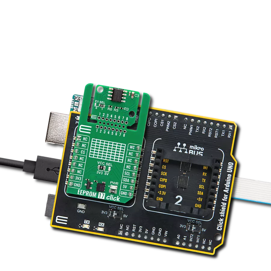
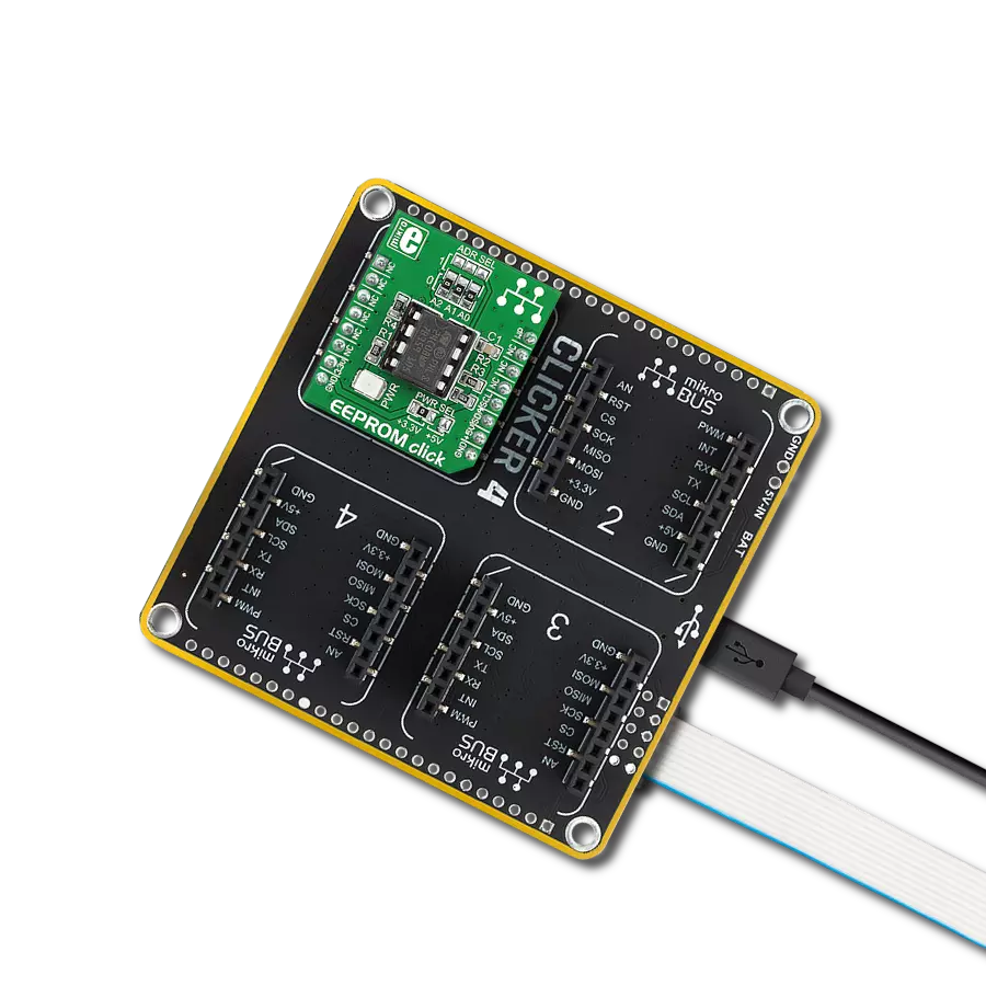
EEPROM Click
Dev. board
Clicker 4 for STM32
Compiler
NECTO Studio
MCU
STM32F767BI
Dependable and long-lasting way to store information in electronic devices with enhanced write protection
A
A
Hardware Overview
How does it work?
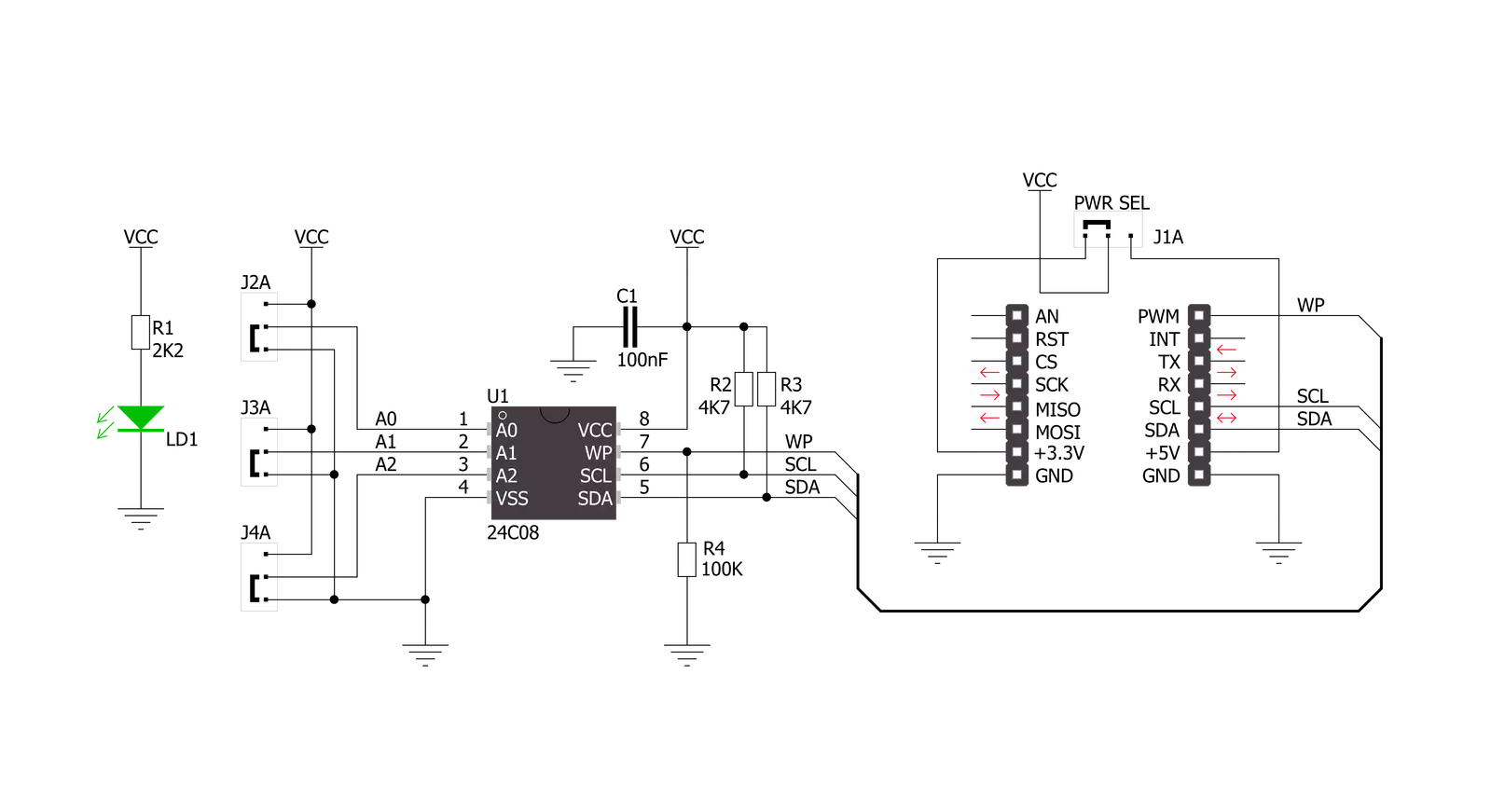
EEPROM Click is based on the FT24C08A, 8Kb EEPROM with an I2C interface and Write Protection Mode from Fremont Micro Devices. The FT24C08A is organized as 1024 words of 8 bits (1 byte) each. The FT24C08A has 64 pages, respectively. Since each page has 16 bytes, random word addressing to FT24C08A will require 10 bits of data word addresses, respectively. It benefits from a wide power supply range and 100 years of data retention combining high reliability and lasting one million full-memory read/write/erase cycles. This Click board™ communicates with
MCU using the standard I2C 2-Wire interface with clock frequency that supports a Fast-Plus (1MHz) mode of operation. The FT24C08A also has a 7-bit slave address with the first five MSBs fixed to 1010. The address pins A0, A1, and A2 are programmed by the user and determine the value of the last three LSBs of the slave address, which can be selected by positioning onboard SMD jumpers labeled as ADDR SEL to an appropriate position marked as 0 or 1. Also, the configurable Write Protection function, labeled WP routed to the PWM pin of the mikroBUS™ socket, allows the
user to protect the whole EEPROM array from programming, thus protecting it from Write instructions. This Click board™ can operate with either 3.3V or 5V logic voltage levels selected via the VCC SEL jumper. This way, both 3.3V and 5V capable MCUs can use the communication lines properly. However, the Click board™ comes equipped with a library containing easy-to-use functions and an example code that can be used, as a reference, for further development.

Features overview
Development board
Clicker 4 for STM32 is a compact development board designed as a complete solution that brings the flexibility of add-on Click boards™ to your favorite microcontroller, making it a perfect starter kit for implementing your ideas. It comes with an onboard 32-bit ARM Cortex-M4 microcontroller, the STM32F767BI from STMicroelectronics, four mikroBUS™ sockets for Click board™ connectivity, a USB connector, LED indicators, buttons, a debugger/programmer connector, two 23-pin headers for interfacing with external electronics, and more. Thanks to innovative manufacturing technology, it allows you to build gadgets with
unique functionalities and features quickly. Each part of the Clicker 4 for STM32 development kit contains the components necessary for the most efficient operation of the same board. In addition to the possibility of choosing the Clicker 4 for STM32 programming method, using an external CODEGRIP or mikroProg programmer connected to the onboard JTAG/SWD header, the Clicker 4 board also includes a clean and regulated power supply block. It provides several ways of board-powering; through the USB Type-C (USB-C) connector using a power supply delivered by the USB HOST (i.e., personal computer), USB wall
adapter, or a Li-Po/Li-Ion battery via an onboard battery connector. All communication methods that mikroBUS™ itself supports are on this board (plus USB-DEVICE), including the well-established mikroBUS™ socket, several user-configurable buttons, and LED indicators. Clicker 4 for STM32 is an integral part of the Mikroe ecosystem, allowing you to create a new application in minutes. Natively supported by Mikroe software tools, it covers many aspects of prototyping thanks to a considerable number of different Click boards™ (over a thousand boards), the number of which is growing every day.

Microcontroller Overview
MCU Card / MCU
Architecture
ARM Cortex-M7
MCU Memory (KB)
2048
Silicon Vendor
STMicroelectronics
Pin count
208
RAM (Bytes)
524288
Used MCU Pins
mikroBUS™ mapper
Take a closer look
Click board™ Schematic
Step by step
Project assembly

Start by selecting your development board and Click board™. Begin with the Clicker 4 for STM32 as your development board.


Software Support
Library Description
This library contains API for EEPROM Click driver.
Key functions:
eeprom_write_page- Page Write functioneeprom_read_sequential- Sequential Read functioneeprom_write_protect- Write Protect function
Open Source
Code example
The complete application code and a ready-to-use project are available through the NECTO Studio Package Manager for direct installation in the NECTO Studio. The application code can also be found on the MIKROE GitHub account.
/*!
 * \file main.c
 * \brief Eeprom Click example
 *
 * # Description
 * This is a example which demonstrates the use of EEPROM Click board.
 *
 * The demo application is composed of two sections :
 *
 * ## Application Init
 * Initializes peripherals and pins used by EEPROM Click.
 * Initializes SPI serial interface and puts a device to the initial state.
 *
 * ## Application Task
 * First page of memory block 1 will be written with data values starting from
 * 1 to 16. This memory page will be read by the user, to verify successfully
 * data writing. Data writing to memory will be protected upon memory writing,
 * and before memory reading.
 *
 * \author Nemanja Medakovic
 *
 */
// ------------------------------------------------------------------- INCLUDES

#include <string.h>
#include "board.h"
#include "log.h"
#include "eeprom.h"


// ------------------------------------------------------------------ VARIABLES

static eeprom_t eeprom;
static log_t logger;

// ------------------------------------------------------ APPLICATION FUNCTIONS

void application_init( void )
{
    eeprom_cfg_t eeprom_cfg;
    log_cfg_t log_cfg;

    //  Click initialization.
    eeprom_cfg_setup( &eeprom_cfg );
    EEPROM_MAP_MIKROBUS( eeprom_cfg, MIKROBUS_1 );
    eeprom_init( &eeprom, &eeprom_cfg );

    /**
     * Logger initialization.
     * Default baud rate: 115200
     * Default log level: LOG_LEVEL_DEBUG
     * @note If USB_UART_RX and USB_UART_TX
     * are defined as HAL_PIN_NC, you will
     * need to define them manually for log to work.
     * See @b LOG_MAP_USB_UART macro definition for detailed explanation.
     */
    LOG_MAP_USB_UART( log_cfg );
    log_init( &logger, &log_cfg );
    log_info( &logger, "---- Application Init ----" );
}

void application_task( void )
{
    uint8_t transfer_data[ EEPROM_NBYTES_PAGE ];
    uint8_t read_buff[ EEPROM_NBYTES_PAGE ] = { 0 };
    uint8_t cnt;
    uint8_t tmp = EEPROM_BLOCK_ADDR_START;

    transfer_data[ EEPROM_BLOCK_ADDR_START ] = 1;

    for (cnt = EEPROM_BLOCK_ADDR_START + 1; cnt < EEPROM_NBYTES_PAGE; cnt++)
    {
        transfer_data[ cnt ] = transfer_data[ cnt - 1 ] + 1;
    }

    eeprom_write_enable( &eeprom );
    eeprom_write_page( &eeprom, tmp, transfer_data );
    eeprom_write_protect( &eeprom );

    Delay_ms ( 1000 );
    memset( transfer_data, 0, sizeof(transfer_data) );

    eeprom_read_sequential( &eeprom, EEPROM_BLOCK_ADDR_START, EEPROM_NBYTES_PAGE, read_buff );

    for (cnt = EEPROM_BLOCK_ADDR_START; cnt < EEPROM_NBYTES_PAGE; cnt++)
    {
        log_printf( &logger, " %u", ( uint16_t )read_buff[ cnt ] );
        Delay_ms ( 300 );
    }
    log_printf( &logger, "\r\n" );
}

int main ( void )
{
    /* Do not remove this line or clock might not be set correctly. */
    #ifdef PREINIT_SUPPORTED
    preinit();
    #endif

    application_init( );

    for ( ; ; )
    {
        application_task( );
    }

    return 0;
}

// ------------------------------------------------------------------------ END
Additional Support
Resources
Category:EEPROM